Category Archives: Blog posts

Consolidated Computer Inc. PDP-8 Clone – Part 7. the memory boards.

Having taken a look at and a brush to, the first few boards, I have come to the memory boards. This machine has 32kwords of 13 bit core memory in two memory modules.

There is a memory bus controller board but I didn’t take a photo of that. I did get photos of the memory modules themselves though.

Top view of the 16kw x 13 bit core memory module.

The memory modules were made by Ampex and have a customer part number containing the initials CCI. This must mean the boards were made specifically for CCI and were not off-the-shelf-items just bought in.

Looking from either side of the module it is not overly obvious that there is any core memory at all. It’s well protected between the two PCBs that make up the module.

Identical in every way?

When I was cleaning the first of the modules I noticed a broken resistor. I struggled to read the value bands so I took a look at the other module, one I hadn’t cleaned at all, and it had the same broken resistor!

Two view of the upper memory board showing the broken resistor

I had a word on the VCFED forums and the view of the team was that the resistors were 510 Ohms. A quick raid of the parts bags and two new resistors were fitted.

Top view of the upper memory board showing the replacement resistor.

Having to part the two boards that make up each memory module gave me the opportunity to take a look at the core memory itself.

The core array is behind a steel plate and a sticker warning me that I was about the void the warranty.

View of the core memory array.

I was very careful when removing the metal plate and I’m glad that I was. This is the smallest core I have see I think. Sadly I don’t have a standard banana for scale but trust me, the cores are tiny.

Close up of the core memory array.

Consolidated Computer Inc. PDP-8 Clone – Part 5 3rd PSU refurbishment.

So we are two power supplies down, one to go. This one is a bit of a monster with three main voltages and two extras.

Top down view of PSU 3 before cleaning.

As with the previous PSUs, this one transforms the mains into lower voltages, rectifies them into DC and smooths them out but like the others it does not regulate the voltages. That’s done by a number of regulator boards at the end of the main card cage.

As with the other PSUs, this one is also filthy and with questionable capacitors.

PSU 3 chassis split into three pieces before being cleaned.

My first job was to split the two halves and see what we are dealing with. As you can see it’s a mucky mess with dirt everywhere and a lot of rust on the capacitor clips.

The capacitors were removed and tested and just like the other supplies, they were fine. They don’t make them like that any more.

The rear of PSU 3. There are 3 PCBs with fuses.
The rear of PSU 3 showing the PCBs and fuses.

The three PCBs were removed and cleaned up. I took a wire brush to the fuse holders and blade connectors, cleaned the fuses and gave the boards a general spruce up.

One or two of the spade connectors had perished and failed when I was removing them so I made some new cables with new spades and replaced some of the other, dodgy connectors.

I replaces a lot of the nuts and washers as they had corroded quite badly. I didn’t replace the capacitor clips as I want to keep as many original bits as possible but I gave them a good sanding to get the rust off before re-assembling the whole thing.

It all went back together and is looking good. The voltages seem OK too!.

Top down photo of PSU 3 after refurbishment.
Here is the finished unit. You can see the capacitors have been cleaned and refitted. As have the capacitor clips and the cables.

Consolidated Computer Inc. PDP-8 Clone – Part 4 2nd PSU refurbishment.

The second PSU is the same model as the first and I went about its refurbishment in the same way.

Firstly, I removed the capacitors. Here was the first problem. One of the smaller capacitors was leaking. Straight over to RS components to see if I could find a replacement. Bingo, next day delivery! Amazingly I found a capacitor of the same diameter with the screw terminals on the same centres with the same screw thread. Marvellous.

The faulty capacitor from the second CCI power supply. The new capacitor is on the right.

I tested the other caps with my capacitance meter and they all looked feasible. I then brought the up, one by one on my bench suply with the current fixed at < 20ma. As each one stabilised at it correct working voltage, I noted the leakage current and this was typically around 0.6-0.8ma. That’s not bad at all for 40 year old caps.

Next the whole unit got a good dust, the terminals and fuses were cleaned with a wire brush and everything was reassembled prior to testing.

The second CCI power supply after refurbishment. The new capacitor is on the left.

On of the wires running from a rectifyer was showing signes of bad corrosion so I made a new cable up with new connectors and fitted that.

I went through the same tests with car tail-light bulbs as I had for PSU1 and they lit up beautifully.

Two down, one to go.

Consolidated Computer Inc. PDP-8 Clone – Part 3 PSU refurbishment.

A photo of the back of the rack showing three power supplys, one on top of the other.
Here are the three PSUs in situ.

It’s time to take a look at the PSUs and see what state they are in. There are three PSUs in this unit, two are the same, the third is different. All are big and heavy.

One of the PSUs removed from the machine showing the dirt.
A grubby PSU

From the photographs you can see a big transformer, two massive capacitors, two lesser capacitors and sundry bits and bobs. So what we have here is a pretty standard, if somewhat large, linear power supply.

This PSU has been sitting for possibly decades and so it the capacitors may need reforming as they can degrade with time. In the next photo, I’ve popped them out and given them a clean. There is no signs of leaking or bulging so it’s so far so good.

One of the larger caps connected to the capacitance meter which is showing 211,000 MFD.
The meter shows there is a lot of capacitance there.

Out with the trusty capacitance meter… All four are giving plausible values so the signs are good. Time to get some power onto them. At this point I connected the capacitors, one at a time, to a variable voltage power supply that had an adjustable current limit. I set that limit to about 20mA and the voltage to about 3v and gave the capacitor some power. At first the current limit came on. This is to be expected. Then the voltage rose to 3.5v and the current limit went off. Next I increased the voltage by a volt or two. The same thing happened. I steadily, over the course of a few minutes, increased the voltage to the full 15v these capacitors are rated at. There were no surprises and no incidents. Few!

One of the two PCBS from the power supply.

Next, I removed the two PCBs, on at a time and cleaned up the terminals and fuse holders with a brass wire brush. These had a layer of corrosion on them and it’s a good idea to get rid of that.

Having cleaned up the terminals and given the whole thing a clean, it was time to put it all back together.

With it all back together it’s time to see if we’ve got a good power supply of a machine for making smoke.

As this PSU is supposed to kick out about 10v (unregulated) I got a couple of 12v car bulbs and added spade connectors so I could use them to put a bit of a load on the PSU. With a linear supply, this is not stricktly needed but it’s a good idea.

Ready for testing.

At this point I admit I was a little scared that I might let the smoke out and so the first test was done in my workshop with the PSU on the end of an extension cable and with me in another room with my finger on the mains switch.

Flick… All is well. A cheery glow through the crack in the door showing that the bulds were lit. I left it like that for 20 minutes before switching it of and moving it back inside for the photos you see below.

Tadaa!

I have measured the voltages and both sides of the PSU are giving a smidge over 10V and according to my ‘scope, there is very little ripple.

Well done our side, just the other two to go now 🙂

To give a clue of the size. A drinks can next to one of the caps

Consolidated Computer Inc. PDP-8 Clone

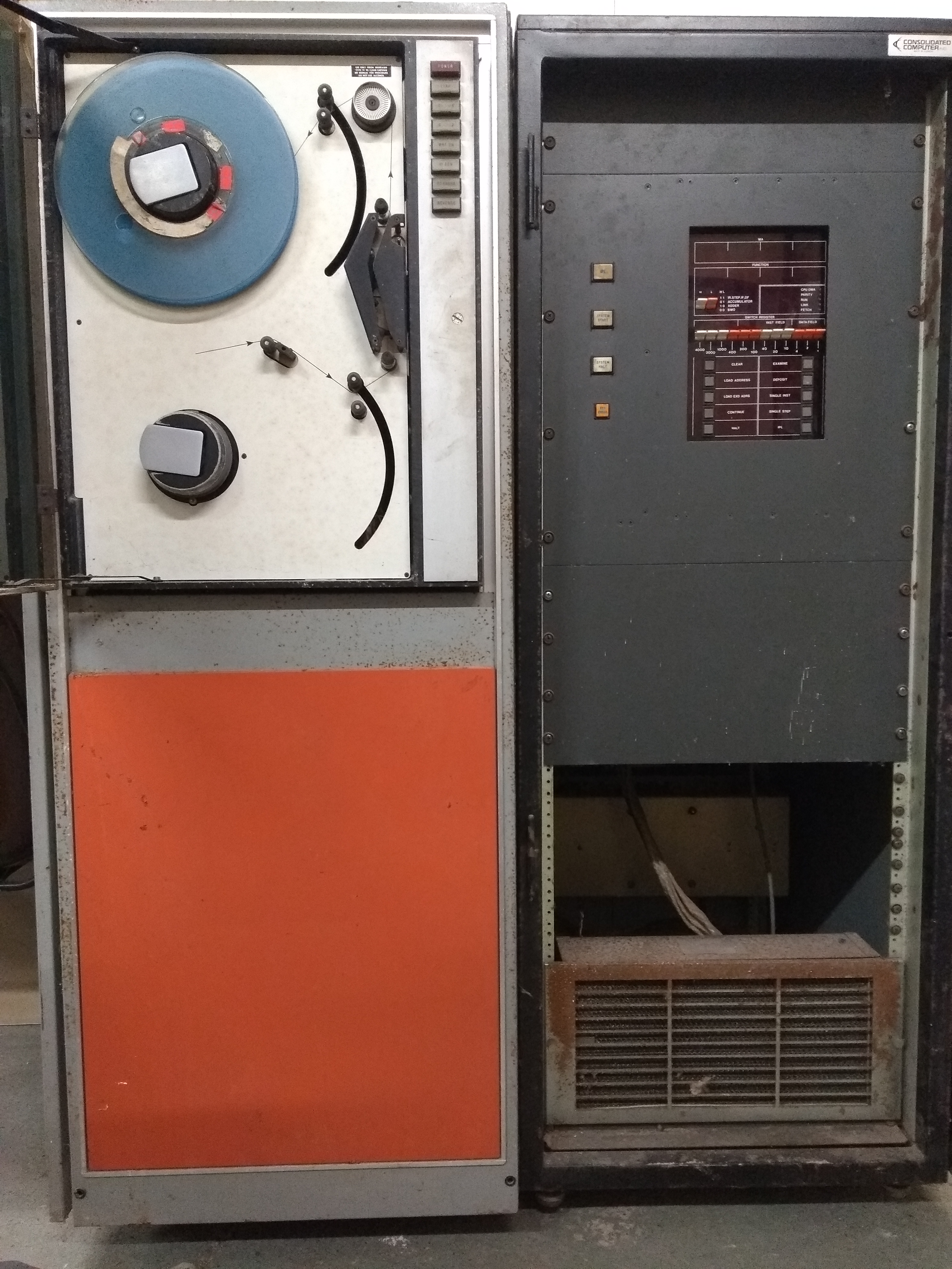
CCi PDP-8 clone in 19 inch rack along side is a 9 track tape drive in a  similar 19 inch cabinet.

Sometimes friends with machines they no longer need will get in touch to pass them on to me. Sometime they have friends who have something they want to get rid of but can’t bear to throw away and so again, I get a call.

I got a message from an old friend of mine, John, to say that a friend of his had a PDP-8 clone that he no longer had space for and was loathed to scrap so asked if I would like it. Of course I said yes please.

At this point all I knew was that it was a PDP-8 clone and it was Canadian. I searched the web for clues but didn’t find anything.

John sent me some photos over and my jaw dropped. I was expecting something like a PDP-8a; A 19″ rack about a foot high. I didn’t expect two chest high 19″ racks, one with the computer, the other with a 9 track tape drive.

Have I been a bit hasty in saying yes?

I did have second thoughts but it’s not everyday someone offers you a PDP and so I couldn’t really turn it down. Luckily I have more than one friend and another, rather generous one, said I could store it in his storage unit for a bit.

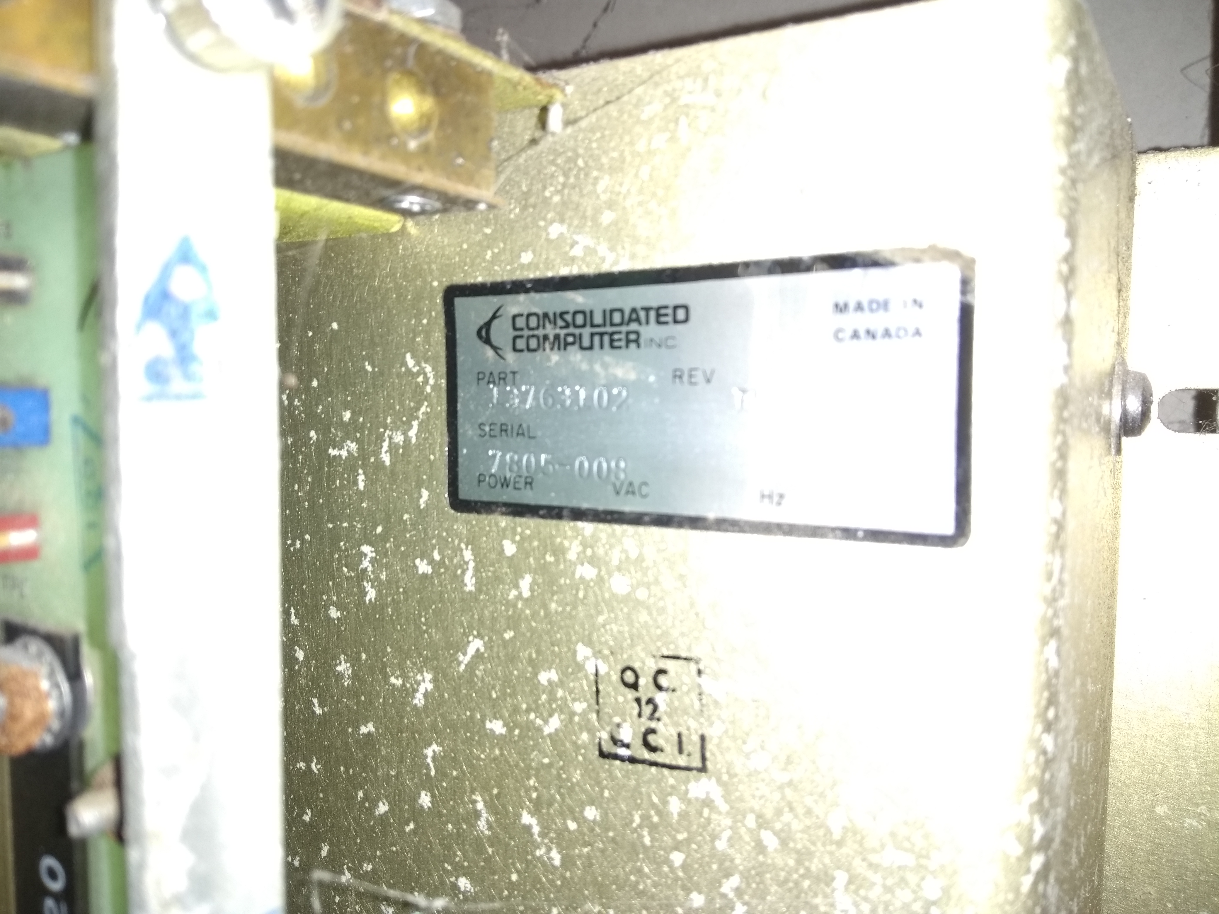
The identity plate inside the cabinet. It shows the CCI logo and text.

From the photos I could see that it was badged as a Consolidated Computer Inc, machine but a lot of searching on the web turned up very little. I found that CCI had been a computer company in Canada and that they were well know. I found that they did indeed make their own computers but I haven’t been able to find anything about the computers themselves. Not even the name of one let alone the specifications.

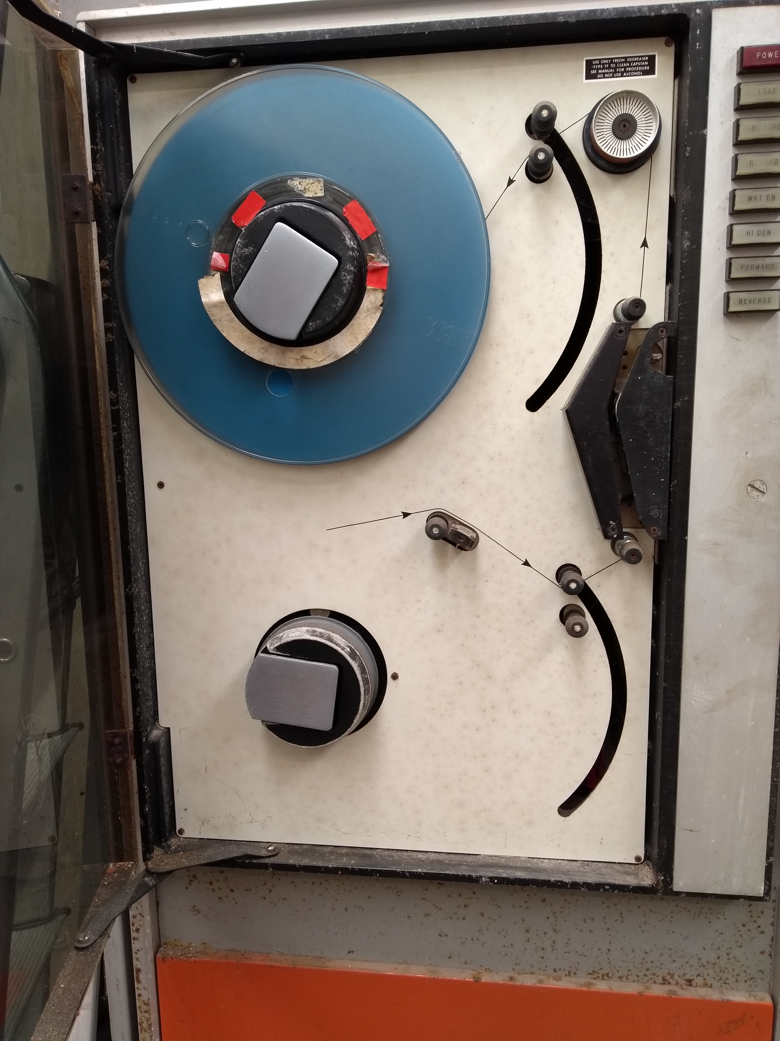
A close up of the 9 track tape drive.

The important thing was to get the machine first. I’d worry about the rest later.

After a brief visit to see the machine in the flesh, I hired a van and got some friends together and we got both cabinets into the back of a van and into the storage unit.

No one was harmed in the making of this journey.

DEC PDT-11/150 – Part 6. Looking at the disk drives.

I am now at the point where the disk controller is passing the RAM test but is hitting another fatal error. The Manual says there is a problem seeking to track 0 and I should replace the defective drive.

That’s more than a little harsh and frankly isn’t an option.

Take a look inside.

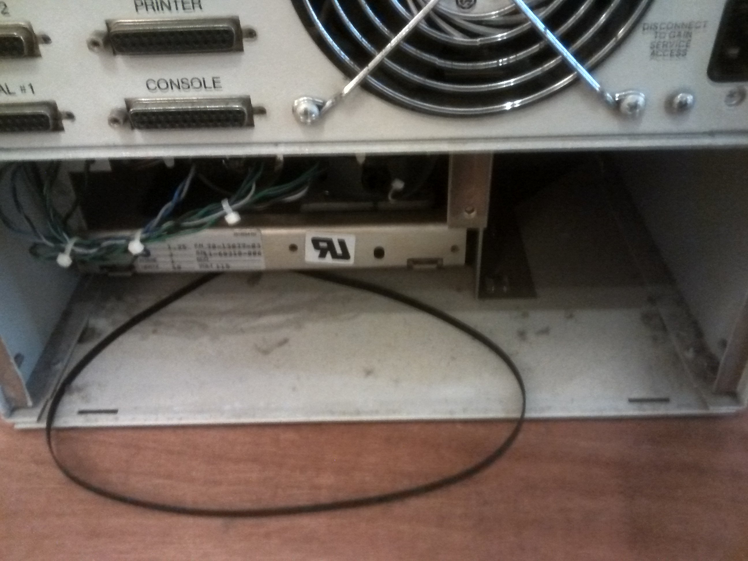
When I unscrew the rear cover on the bottom disk drive I am greeted with this image..

It seems unlikely that someone packed a spare drive belt 😉

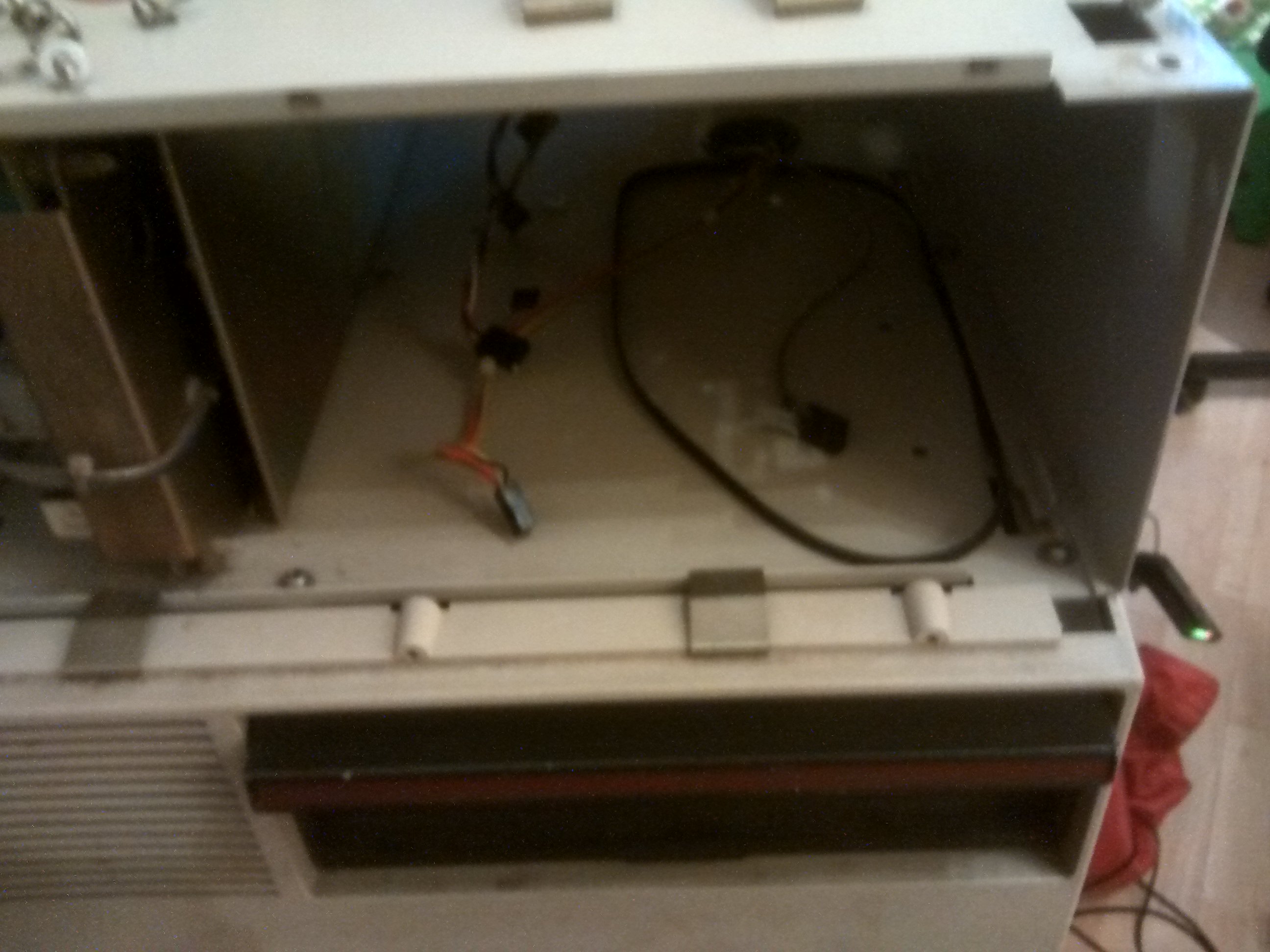
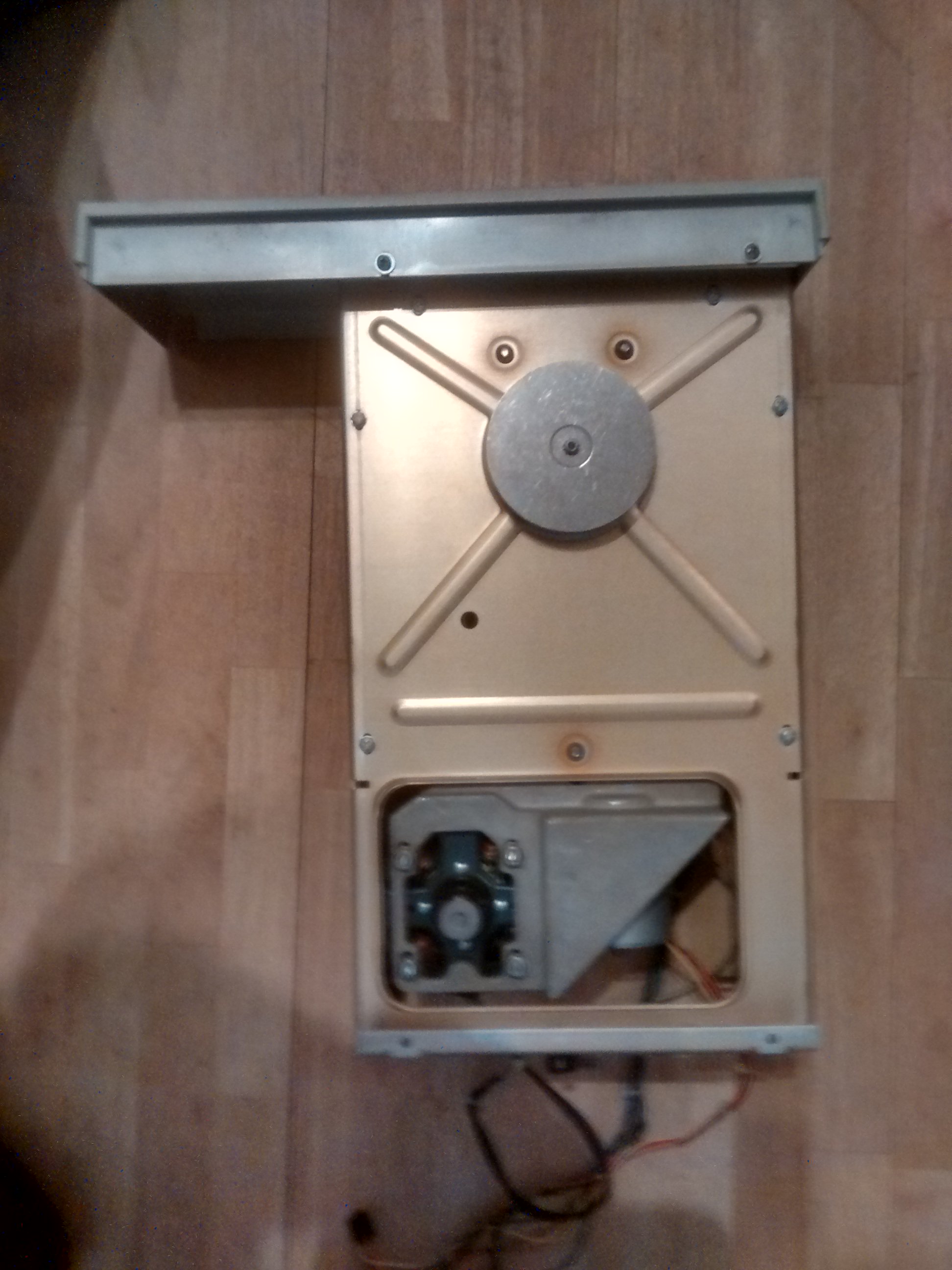
There is nothing so obvious looking in to the top drive but on removing the drive I get a similar story.

This is the top drive bay with the drive removed.

You can clearly see that both drive belts have fallen off their respective pulleys.

So what has happened is that the belt have lost their condition over the thirty or so years that they’ve been on the drives and just don’t grip any more.

What to do next?

As you can imagine, new belts from DEC are not an option, so I need to improvise a little.

Snipping through one of the belts and measuring gives a length of 588mm and so a diameter of 558/pi which equals 188mm.

Record deck belts are available around that diameter and I have one on order but the suggestions on-line say they aren’t a good option as they tend to be stretchy.

I have also found a flat industrial belt at 590mm length and so I’ve ordered a couple of those.

I’ll let you know how I got on.


DEC PDT-11/150 – Part 5. The new disk controller RAM arrived.

In the last post I had found a faulty RAM chip on the disk controller board and ordered a replacement from a supplier on ebay.

Well, the part arrived Today and one fitting, the error lights on the disk controller went out… For a while.

I can confidently say that we are past the RAM errors and it is trying to boot but the drive makes a lot of stepping type noises and doesn’t settle down for quite a while. Then the some LEDs on the main board and the controller board light up.

This is what we have this time.

This time, according to the manual, they don’t mean RAM error. This time they mean.

1, 4&5 on the main board.

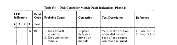
This manual says that this “Verifies that the second pass of the disk drive diagnostic was successfully completed. If an error is indicated, refer to Table 5-4 for the possible fault indicators on the Disk Controller module test phase 2.”

1 on the disk controller.

The manual says “Verifies the position of the disk drive 0 head after a restore command is issued.” and the course of action is “Replace defective drive 0 or module.”.

Replacement isn’t an option so I’m going to have to go in and see what’s occurring.


DEC PDT-11/150 – Part 3. Healing hands.

I was preparing to share with you all my efforts driving the ODT with PDP11GUI.

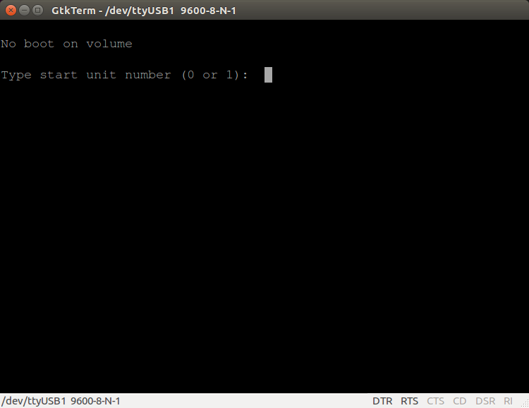
I have been using it to assemble Marco-11 assembler code and squirt it across to the PDT’s ODT. The problem is that when I came to fire up the machine to do a bit more and maybe take some screenshots I can’t get to the ODT because the machine is now asking for a boot floppy!

So that’s how you get it to try and boot. You write about it on your website and shame it into trying. I am part delighted and part deeply suspicious. Computers don’t heal by themselves.

I kind of miss the ODT to be honest. At least with that I could make some progress and fire octal code at it.

So what happens now?

Not much. It doesn’t seem to touch the disk drives when I answer its question. It just tells me there is “No boot on volume” and asks me again. It doesn’t even seem to rattle the disk.

The funny thing is, when it only went to the ODT, it seemed to get the drives to seek to track zero and it’s stopped doing that now. Curious.


DEC PDT-11/150 – Part 2.

In the last post I described the PDT-11/150 a little bit and the state of play. It was showing signs of life but not talking to me.

It turns out the cable wasn’t right. Switch to a new cable, fire up GtkTerm and we’re on the right lines.

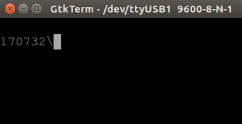
What we have here is the ODT display. It doesn’t look much but it shows us that the machine is alive and conscious.

Main switch settings.

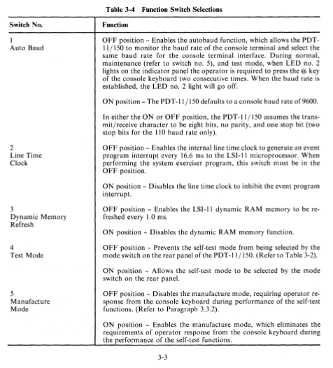
There is a five switch DIL pack on the top board that sets various options for the machine. The manual gives the following explanations:-

IT seems a little odd that the switch labelled “Auto Baud” should be set to off to turn Auto Baud on. Really? Ah well.

Mine are set as follows:-

  1. ON – Auto Baud is disabled. Baud rate is set to 9600.
  2. ON – Line clock is disabled.
  3. OFF – Enable the DRAM refresh.
  4. OFF – Disable the test mode.
  5. OFF – Disable manufacturer mode.

Setting the switches this way I can get to the prompt you see above.

I have tried getting into the test mode but it doesn’t seem to work on my machine. I wondered if the self test at power up is failing and dropping me into the ODT but the error light on the front goes out so I guess not.

I haven’t turned on the line clock as I don’t know yet if I need an interrupt handler for it. Clearly we need DRAM refresh and fixing the Baud rate at 9600 is just A Good Thing (TM).

Booting?

Now here’s a thing. I can’t find any information about how to get this thing to read a floppy. The manual describes setting the switches to get test mode. It says how to insert a floppy and how to handle them safely but nothing on how to boot the machine.

I’ve looked at both the technical manual and user guide (thanks to Bitsavers) but there is nothing.

A little test.

Although I can’t boot from floppy, I can fire in code using the terminal and things are starting to look brighter.

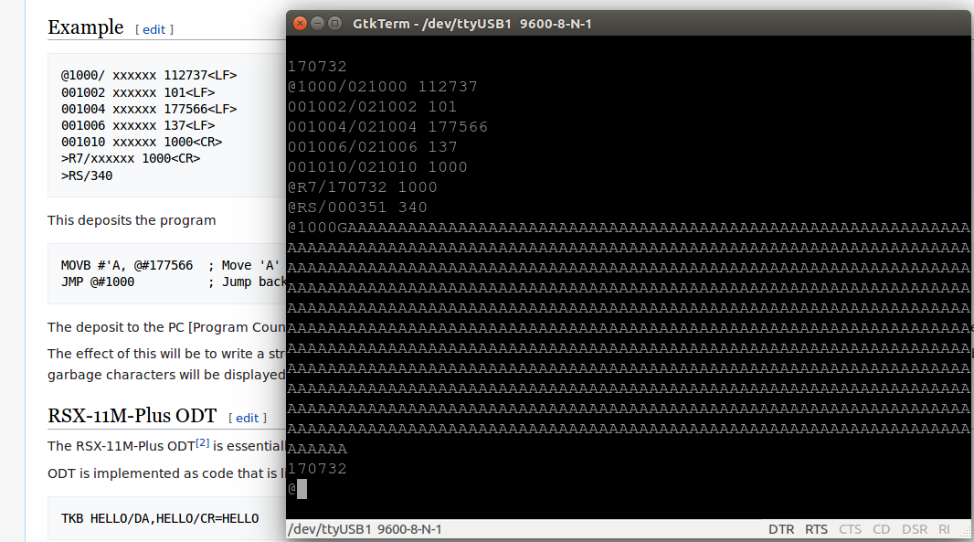
Here is an example from the ODT page on wikipedia.

This fires the letter ‘A’ at the console port as fast as it can and only stops when you press the reset switch.

Tada!


RetroChallenge 2017/10 – Last day

So another Retrochallenge comes to a close.

What did I do lately?

Well, in the last 24 hours I have tested all of the 74 series chips, with the exception of the 74LS163 (my tester won’t touch them). All were fine, no problems at all.

I swapped the 74LS 163s around to see if the fault moved. It didn’t.

I swapped the 81LS97s, again to to see if the fault moved. It didn’t.

Where are we?

It’s hard to tell.

My newest addition is still not playing ball and I’m stumped as to why, but, that’s not the point of Retrochallenge. The point is to dust off this old kit and have a play and I’ve certainly done that 🙂


Roll on RC2018/4