Retrochallenge 2016 – Decisions decisions.

Retrochallenge 2016 will soon be upon us. This month long chance to dust off old kit and play about a bit is always great fun and a chance to get round to stuff I’ve wanted to have a crack at for ages.

Tradition dictates that I try in all earnestness to achieve something but I don’t hit my target. I’m not sure that it matters.

So, what to go for this time around? I’m not too sure yet. I certainly have a number of loose ends to tie up. I also have a whole load of new threads to pick at.

I quite like the idea of getting a SCSI/SD card adapter working on my PDP-11. I’ve got as far as plugging it in. Could January be its month?

Last month I found out about DEC’s T11 chip. This was

"a microprocessor that implements the PDP-11 instruction set architecture (ISA) developed by Digital Equipment Corporation. The T-11 was code-named "Tiny". It was developed for embedded systems and was the first single-chip microprocessor developed by DEC."

I’ve found a few designs for systems that use it, including DEC’s own development board, and I rather like the idea of building a small single board computer based on that design. A bit like the designs that Grant Searle as published for other retro processors.

Also, I promised myself that I’d spend some time on the DEC Robin AKA VT-180 CP/M machine that’s been on the shelf of “good intentions” for a few years now.

Oh well, still a few of weeks to choose before kick-off on Jan the 1st.Β  Wish me luck.


EACA Genie 3 EG-3200

151127-IMG_20151127_193556730EACA began making computers with the Genie name in 1980. The first model, the Video Genie System started EACA on the road of Z80 based machines that were mostly compatible with the TRS-80 Z80 based machines. I haven’t found any mention of Radio Shack’s opinion of having their machines cloned, which is a bit odd.

Could that have been the first cloning? Probably not. but I digress.

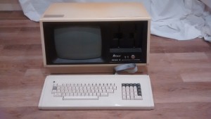
This machine is the Model 3 (EG-3200) and it’s a EACA’s version of the TRS-80 model 3. It hit the market in mid 1982 and while it is functionally close to the TRS-80, it does have some differences.
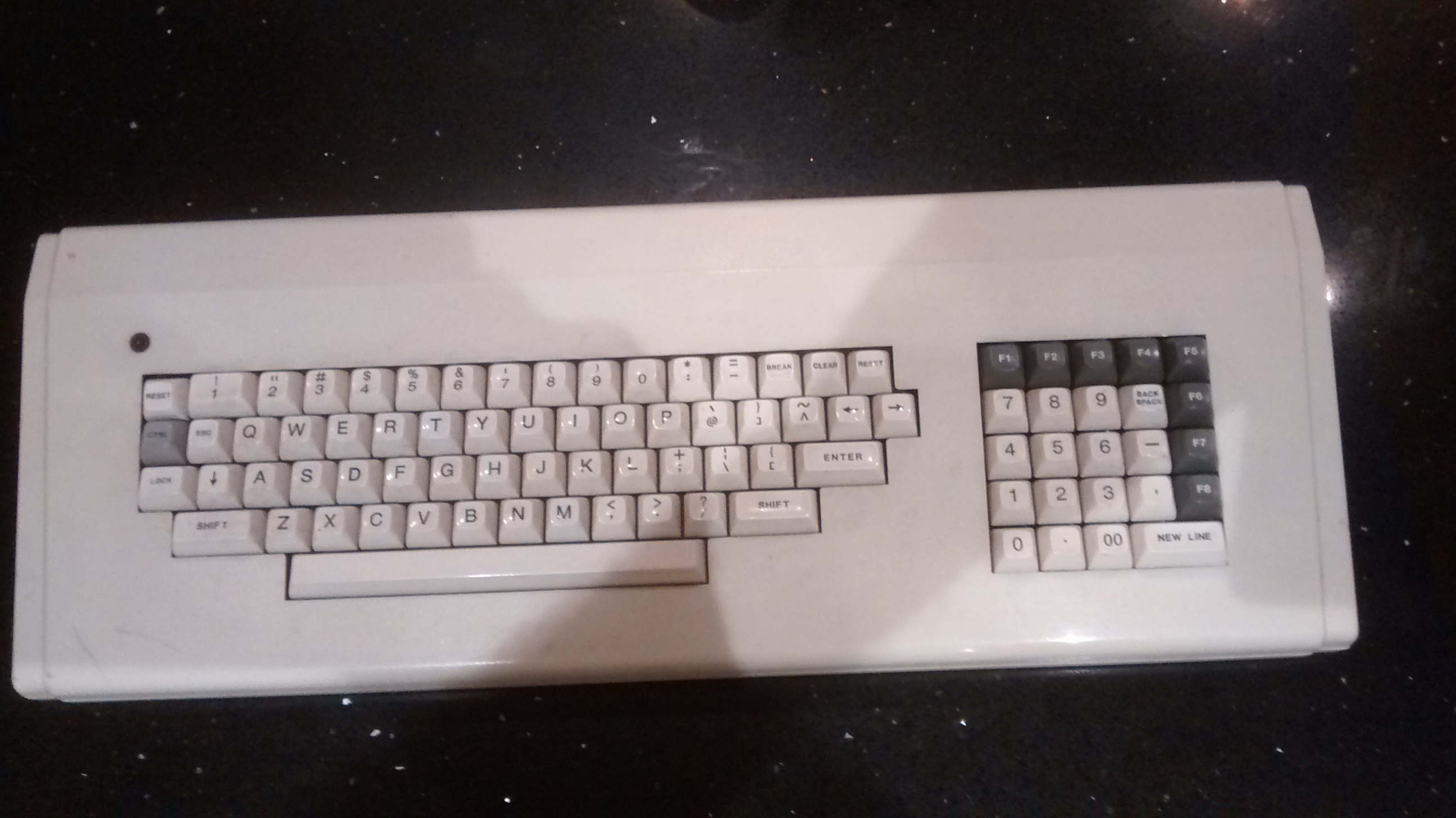
151127-IMG_20151127_194656547Keyboard.

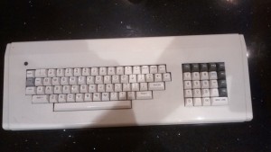
Firstly, you can see that there is an external keyboard. 86 keys including a number pad. This is connected to the main unit by a ribbon cable and a connector more used to being inside a computer than outside. The use of ribbon cable wouldn’t be acceptable now for cost and electrical noise reasons but it was not unusual back then.
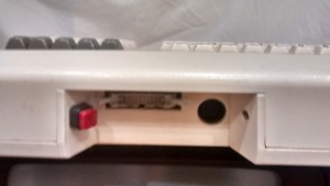
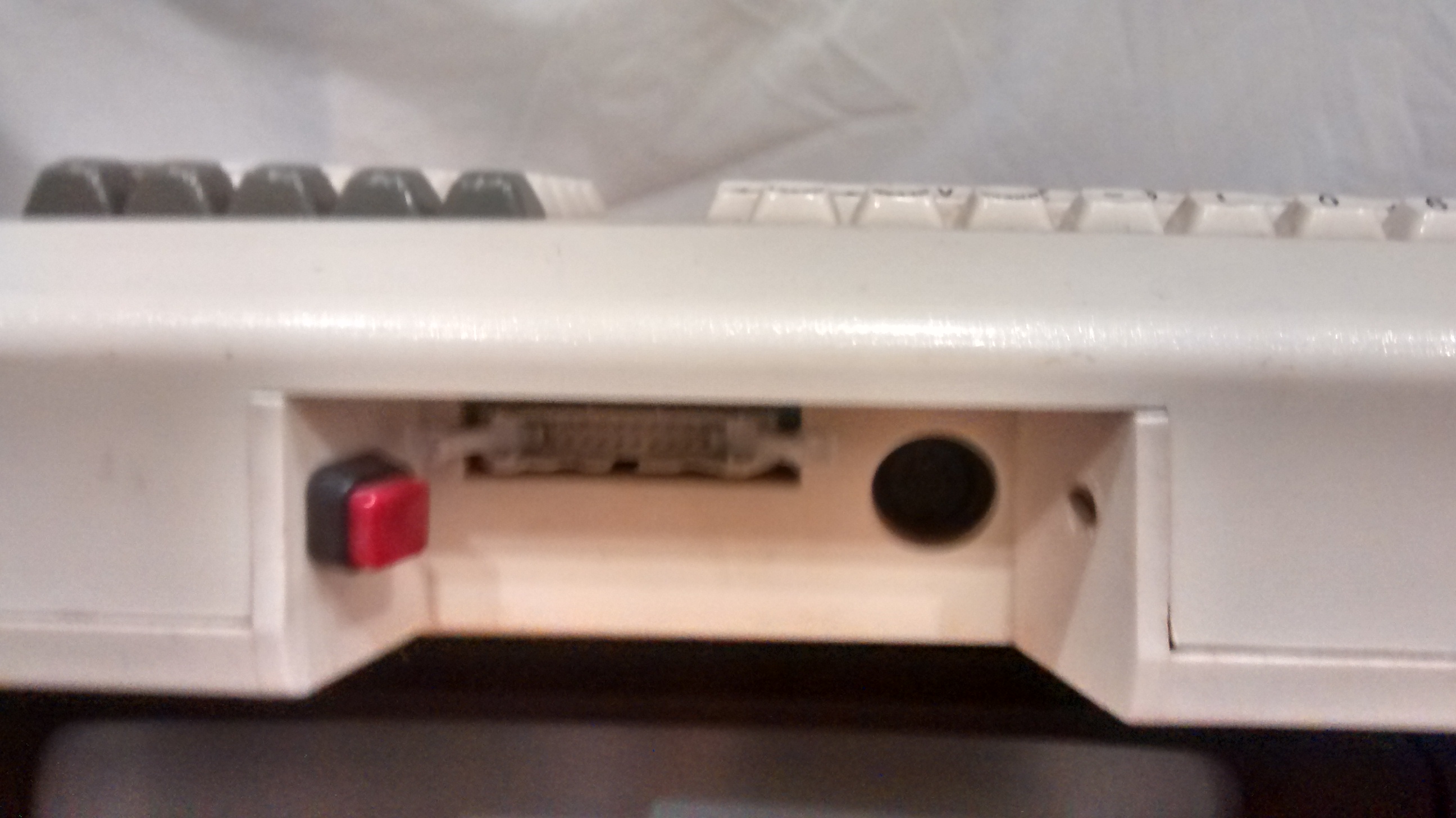
151127-IMG_20151127_193643199_HDRUnusually, mine has been modified to add a push button at the back. The reason for this? No idea… yet.

Main unit.

The main unit houses a monochrome CRT, a pair of floppy disk drives and a number of boards in a card cage that make up the computer proper.
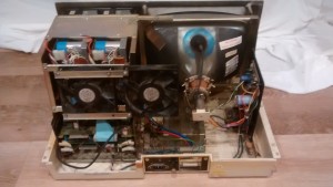
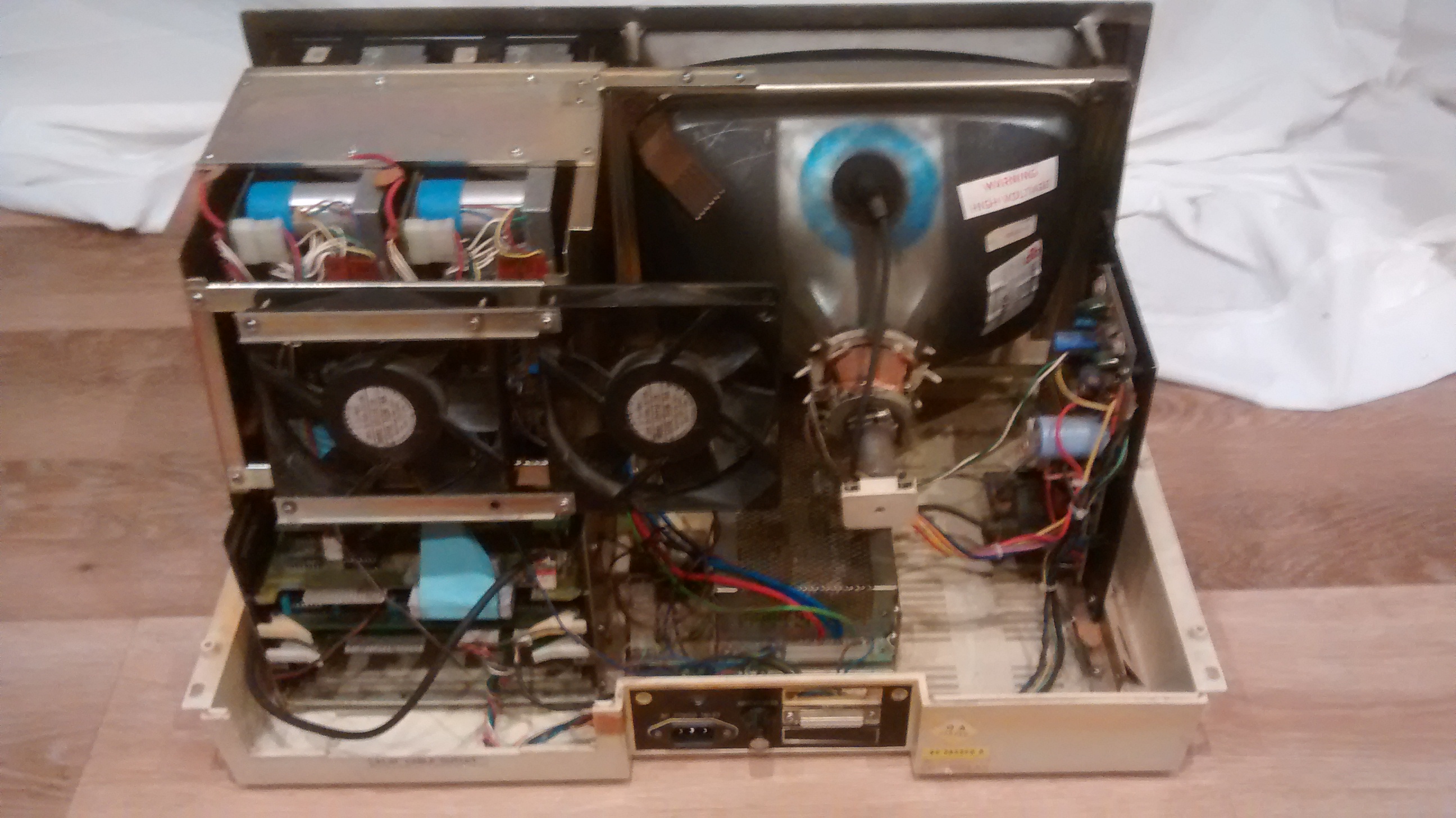
151127-IMG_20151127_193745220In this photo you can see the floppy drives in the top left and a card cage below them. clearly, this is a big difference from the TRS-80 family. The TRS generally had one main CPU board and an extension board holding the disk controller and perhaps extra RAM. Here we have the various function split across three boards sharing a common backplane. It’s quite a nice move.

The power supply is sitting in the middle of the bottom of the case.

Mechanically the machine is quite nice. The lid is held down by machine screws rather than the more common self tapping screws. The CRT is held into a metal frame by suitable screws. The front bezel is also attached to the steel frame and has its own screws. From this point of view it’s quite nice.

The surprising thing for me is the the electrical connections throughout the machine seem shoddy. The mains cables to the PSU are soldered onto the pins. Normally you would see a connector. The wires from the VDU controller are soldered onto the Samsung CTR board. Why not use connectors? Cheap perhaps? Didn’t know better? I’m not sure but this looks so poor compared to the mechanical arrangements.

CP/M-80.

Unlike the TRS-80 model 3, the EACA Genie 3 came supplied with CP/M-80 and NEWDOS-80. CP/M out of the box. Terrific.
151127-IMG_20151127_193624401Mods.

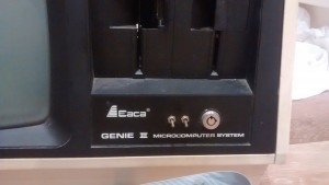
Here you can see that my machine has been modded again. This time two toggle switches under the floppy drives. At the moment I don’t know what these do but I’m thinking perhaps 40/80 track switch and single/double density. However, they could be write protect switches but as the drive has them build it, that seems unlikely. Time will tell but the wires definitely go off to the disk controller card.

State of play.

Does it work? No.

But it’s not a hopeless case. the first time I put power into the machine, I did’t have the keyboard connected and if sat there flashing the drive lights in turn, repeatedly, but nothing on the screen. When I turn on the machine, with the keyboard, it selects the first drive for a while and then the light goes out. Still nothing on the screen.

I haven’t looked at the video signals with a ‘scope yet but I didn’t notice any static build up on the face of the tube or hear anything from the CRT area so I think there may be a power problem with the monitor.

Here starts another adventure.

RML380Z – and you’re back in the room.

I replaced the 74s32 with a 74ls32 (the closest replacement I could get) and the machine didn’t leap beck into life.

Disappointed doesn’t come close.

I walked away for a few days and came back to it and it came up.151108-IMG_20151108_141830344

I powered it of and on again and it didn’t. That’s a bit odd.

Out came the boards and chips were pressed into sockets. Power up again and Bingo! Off and on and still OK.

So here’s the question… Was it the keyboard adapter that caused it to fail or was it just coincidence? I’m not sure if I dare find out yet.

RML380Z – One step forward…

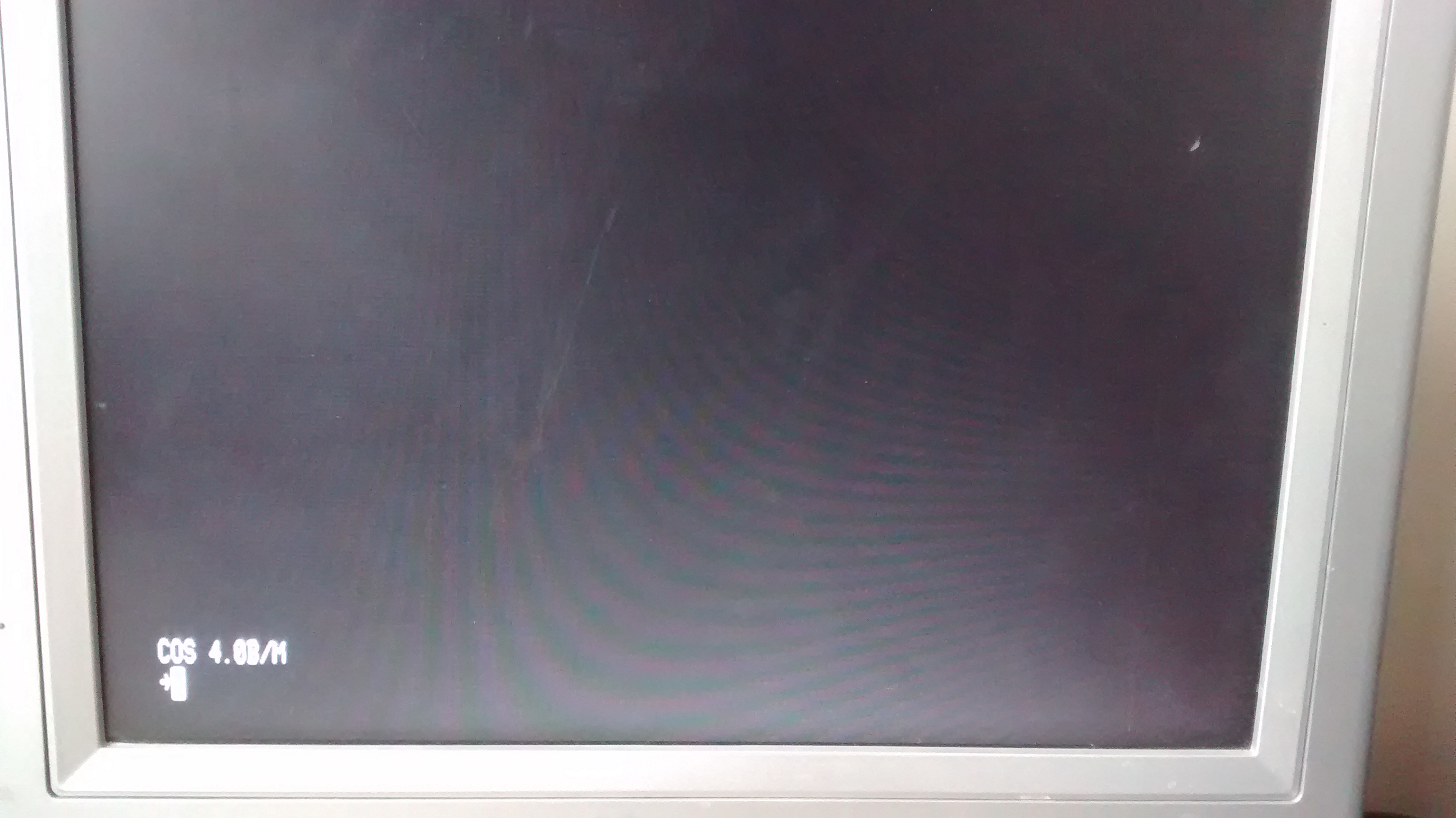
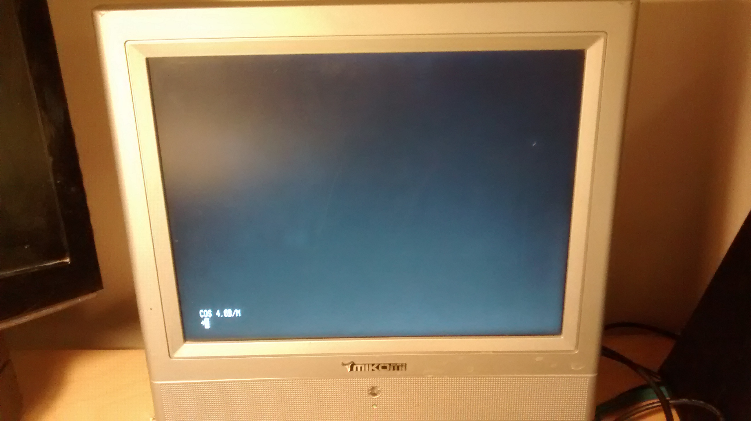
In my previous post, things were looking up. I had replaced a couple of faulty chips, re-seated all of the chips on the CPU and Video cards and swapped out the RAM from the CPU card with the expansion cards and now my 380Z was getting to the COS prompt.

All I needed was a key press. Specifically, I needed a ‘B’. Sadly, I don’t have a keyboard.

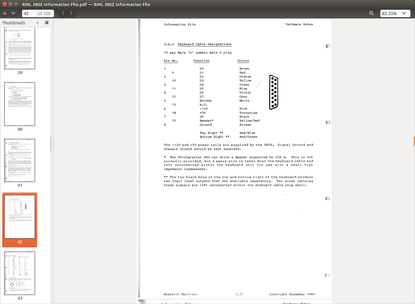
Screenshot from 2015-10-25 20:08:23Looking at one of the technical documents shows that the keyboard interface is a simple 7 bit parallel interface with a strobe. How hard can it be?

Arduino to the rescue?

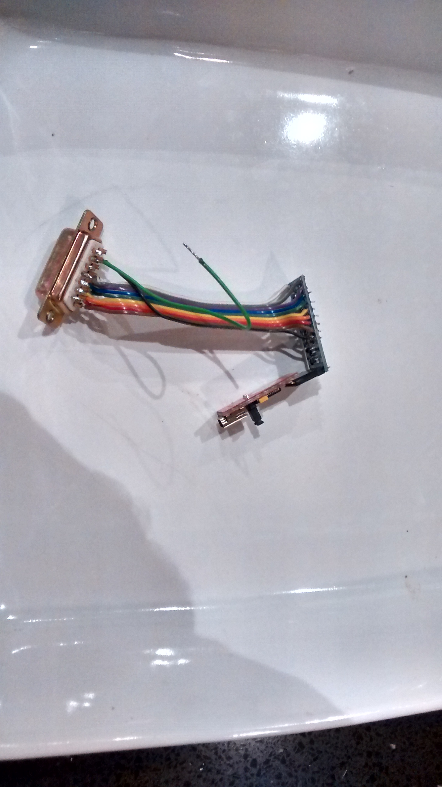
151025-IMG_20151025_182536405_HDRI had a supply of Arduino pro mini compatible boards and so I set to building an interface and a sketch to drive the circuit. The idea is to catch characters from the ‘duino’s serial port and squirt them out of the parallel port the way the 380Z likes them.

Not so Fast.

I plugged in the board and nothing happened. I restarted the machine and nothing happened again. Just a blank screen, no COS prompt. Doh!!.

I went over the circuit for the interface again and a again and couldn’t find anything wrong with it. It does appear to have toasted the 380Z though.

A clue?

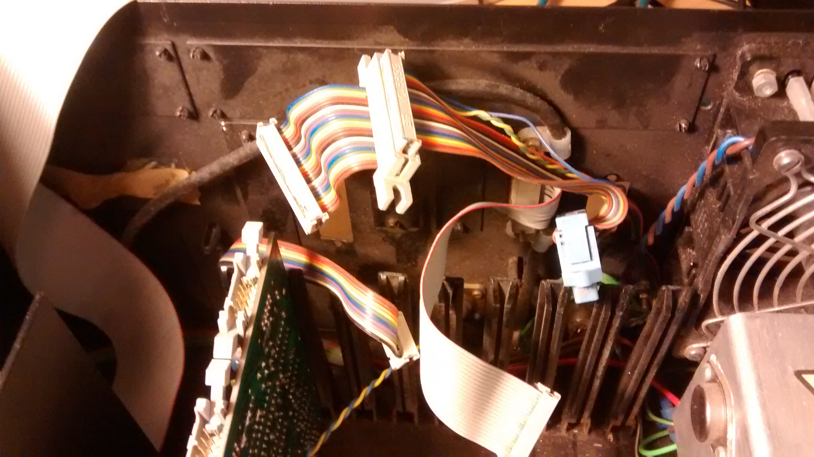
By coincidence I have just been to the Centre for Computing History in Cambridge and they have a 380Z on a table. I quick word with Jason who runs the place and I have a look inside. Their machine has a different keyboard cable to mine. Mine has an additional connector in-line with the cable. Theirs doesn’t. Sadly, I didn’t take a picture of theirs but it definitely only had one connector at each end.

151025-IMG_20151025_182559575You can see from the photo here that mine has the additional connector. After that connector, wires go off in the direction of the PSU. I’m wondering if mine has been modified for some reason and that has made it incompatible with my relatively simple interface.

I’ll have to trace where all of the wire go and see if that’s significant. I could also do with confirmation that the keyboard ribbon should be straight through.


RML380Z – Signs of life.

151014-IMG_20151014_213240378OK. Getting excited now πŸ™‚

I swapped the 4116 DRAMS from the CPU board with those on the RAM expansion card. And now… Ta Daa. I haven’t’ tried the RAM expansion card yet and so I don’t know if the chips are faulty or just dirty and re-seating them has done the trick but so far so bloody brilliant. I’ve waited 35 years for this.

πŸ™‚

RML380Z – Arrival of the new chips.

A small envelope arrived in the post Today. A tube of 74LS00 and 74LS393 to replace the ones identified as broken by my chip tester. The chip tester says that the new 393s are also faulty so I suspect the tester is a little flaky. Anyway, on with the show.

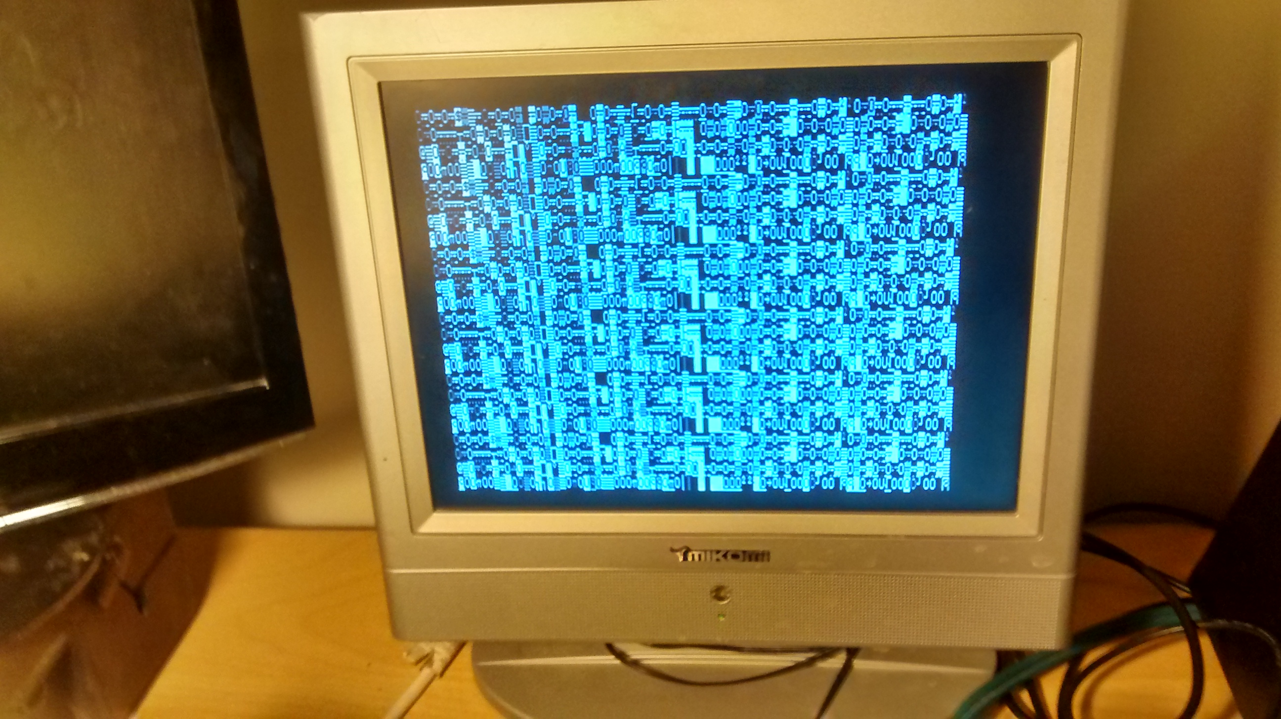
151014-IMG_20151014_180418795There has been some improvement but not a fix. I also reseated the chips that were not tested (ROMs, DRAMs etc.). I moved the 4116s around too to try and flush out the problem.

Back to square one?

It looks a bit like it. I think this might be a clue.

151014-IMG_20151014_181530814_HDR


380Z Repair – Send for supplies.

151009-IMG_20151009_162919625_HDRToday I received an IC tester through the post. Yay.

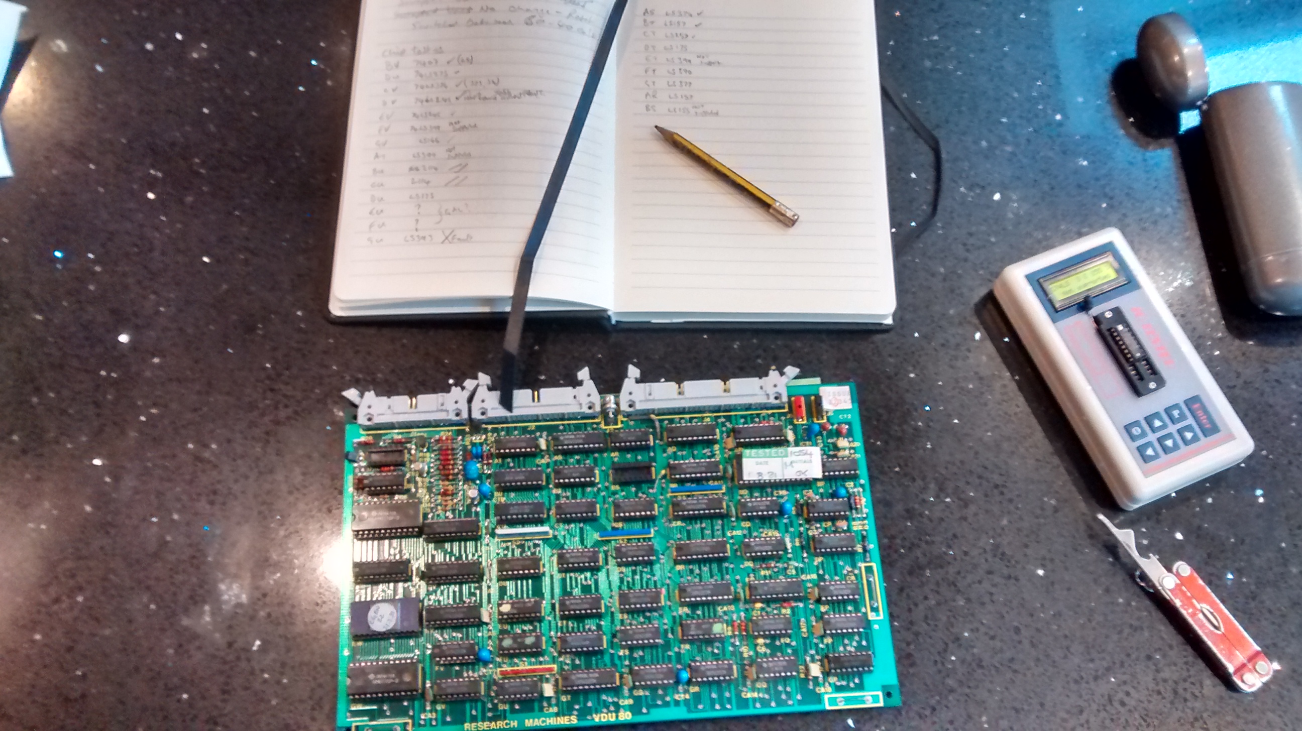
this is an important bit of kit for me. All I have to do is remove a chip from its socket, dorp it in the tester and press ENTER. This little gadget identifies and tests the chip in a fraction of a second. Crikey.

I’ve worked through the VDU and CPU boards and found one faulty 74LS393 counter on the VDO board and a 74LS00 NAND gate on the CPU board. Hopefully these are the source of my problems. If not, I’ll keep looking.

Supplies are on order. I’ll keep you posted.


380Z Repair – Another try.

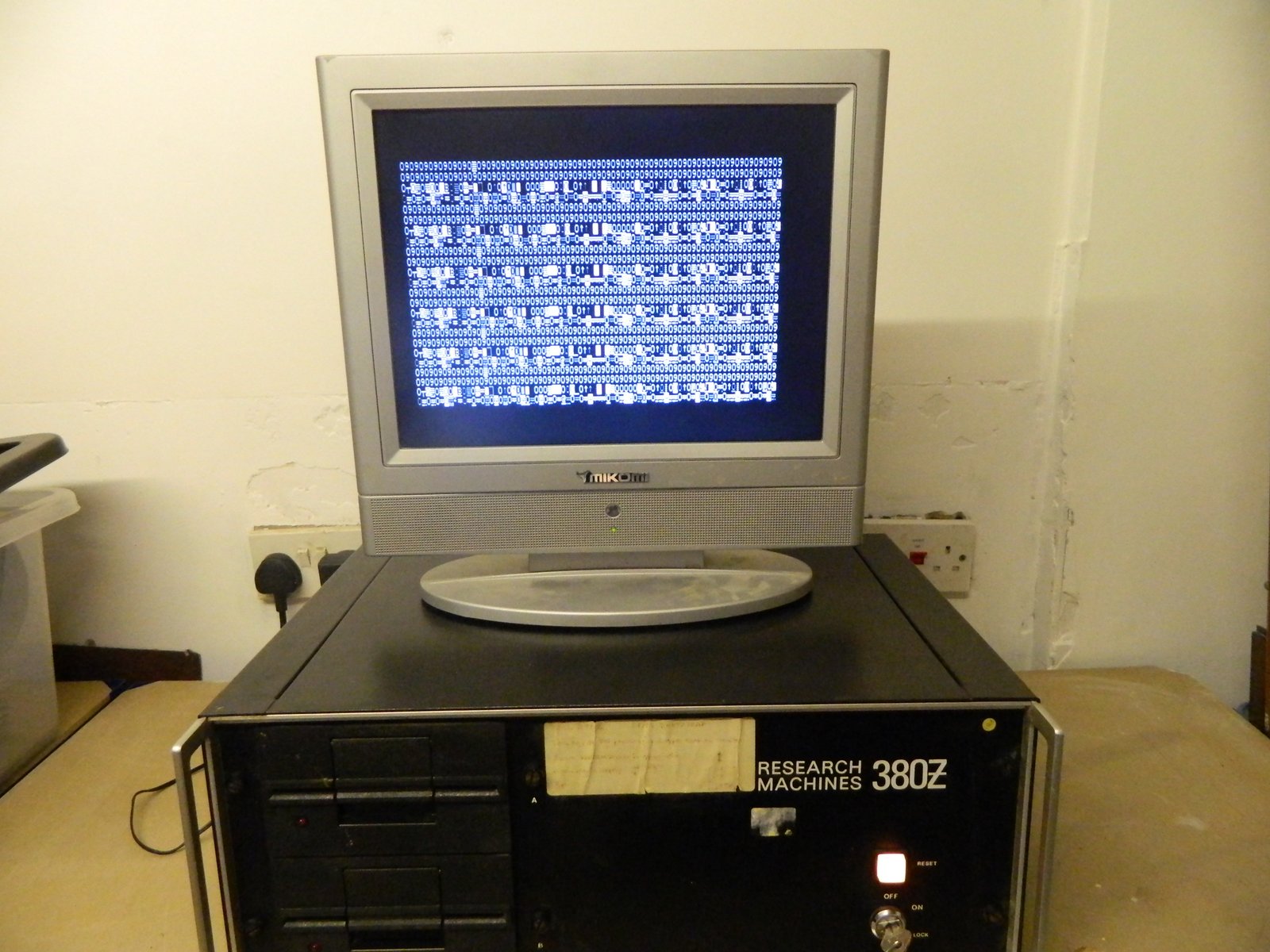
After a break of a couple of years I’ve decided its high time I had another go at repairing my RML-380Z. You can read about this machine and my previous attempts here.

A quick recap… 53e525645f5aa2c829d66d1d878e69f6

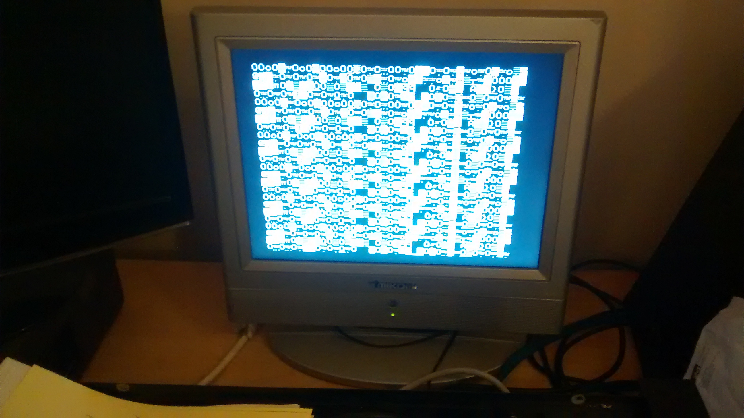
When I power the machine on I get a a fixed, pseudo random image on the screen but no other signs of life. I’ve re-seated chips in their sockets and swapped the RAM chips around the board but that’s about it.

It has been suggested that I swap matching logic chip to see if that gives any clues…