Spoiler alert. If you don’t want to know what happened, don’t read the title of this post. Too late.
I got home tonight to find that the new keyboard cable for the BBC Micro had arrived. I plugged it in and just a long beep. Doh!
I then did a lot of looking and checking and found that the left most pin on the motherboard had been bent over at some point. I bent it over and tried again. This time, beep, beep and a banner and prompt.
Yea!
However. It hands after a minute of so. A restart and it only lasts seconds and so I’m convinced that it’s thermal. More investigation needed.
As I said in my previous post, the BBC micro was showing some signs of life but wasn’t booting. I sent off for capacitors for the PSU and they arrived. In with the screwdrivers.
Just three screws from the back and the PSU is on the bench. The unit itself is a little trickier to take apart but not difficult.
Be aware there can be high voltages on the board even when it’s out of the computer and disconnected from the mains.
The easiest way is to pop out the switch and external power connectors first. A flat bladed screwdriver will let you press the springy plastic lugs down and then they push out. Look out for the two green earth leads bolted inside.
Then the unit is out.
I think two of the caps had already been changed which just left the electrolytic at C9 (IIRC). This looked bad and was bulging so out it came.
I reassembled the machine but to be honest I wasn’t expecting a change as I think the fault is caused by the keyboard cable and not the PSU. Changing the cap was a safety measure. Hopefully the cable will arrive in the next day or two.
Now be honest. Is there anyone aged between 35 and 55 in the UK who hasn’t used a BBC micro? This little machine was massive over here. They were everywhere, Rugged, dependable, terrific BASIC interpreter, in-line assembler. The list goes on and on.
This machine came to me from my friend Tris. He is another retro-computer collector but unlike most of us, knows when enough is enough and decided the his BBC Master would be enough and gave me this non-functioning unit.
Under the lid.
An Issue 4 mother board.
The machine has an Issue 4 mother board. I think this is a bit unusual. From memory I think Issue 3 and Issue 7 were the most numerous. Another thing it has is a lid lined with aluminium foil. Curious. I wonder if it gave out too much interference for the TV or somesuch.
Aluminium foil inside the lid. RFI problems perhaps. Or just to keep it fresh?
Power up.
When power is applied, I here one beep. There should be two. With a monitor connected there is a nice raster on the screen and a flashing cursor. Nothing more.
The keyboard connector has seen better days.
A look inside shows that the keyboard connector is very tired, with a number of connections broken. I tried to reconnect the broken ones. There was a brief bit of activity as the words “BBC Micro…” started appearing on the screen. _VERY_ Slowly. I tried a reset and things got worse. The beep didn’t end.
Now I’ve seen that the machine is close to working and so my strategy is this.
Replace the keyboard cable – I have one on order.
Replace the capacitors in the power supply – It won’t hurt.
I’ve been tinkering with my recently aquired Sharp MZ-700. I’ve solved the problem of getting programs into it by playing it WAV files from another machine using a cheap car cassette adapter and it’s working like a good’un.
Sadly a couple of the key switches are broken and to my surprise they aren’t individual switches. I’m on the lookout for bits and bobs to fix it.
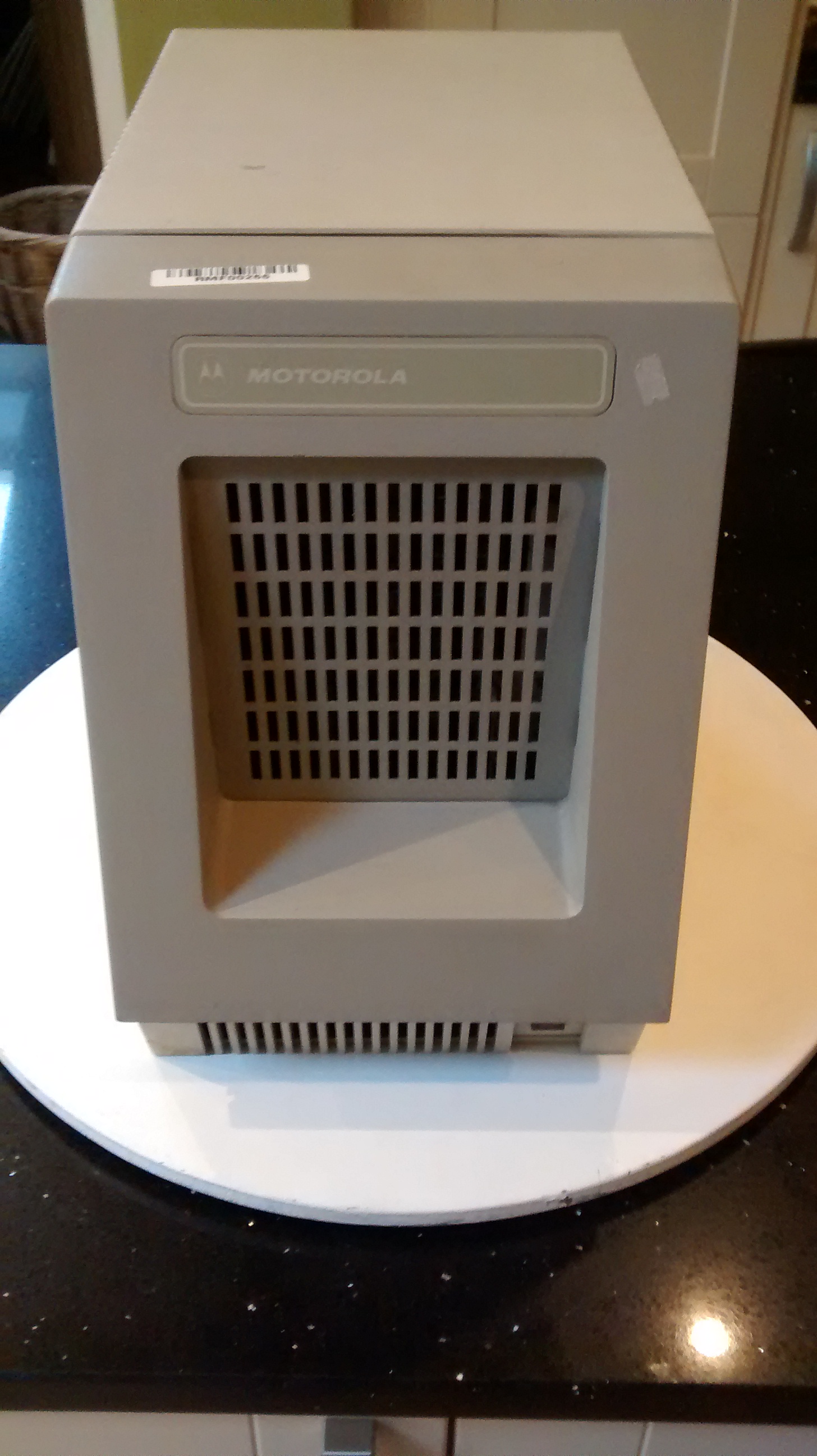
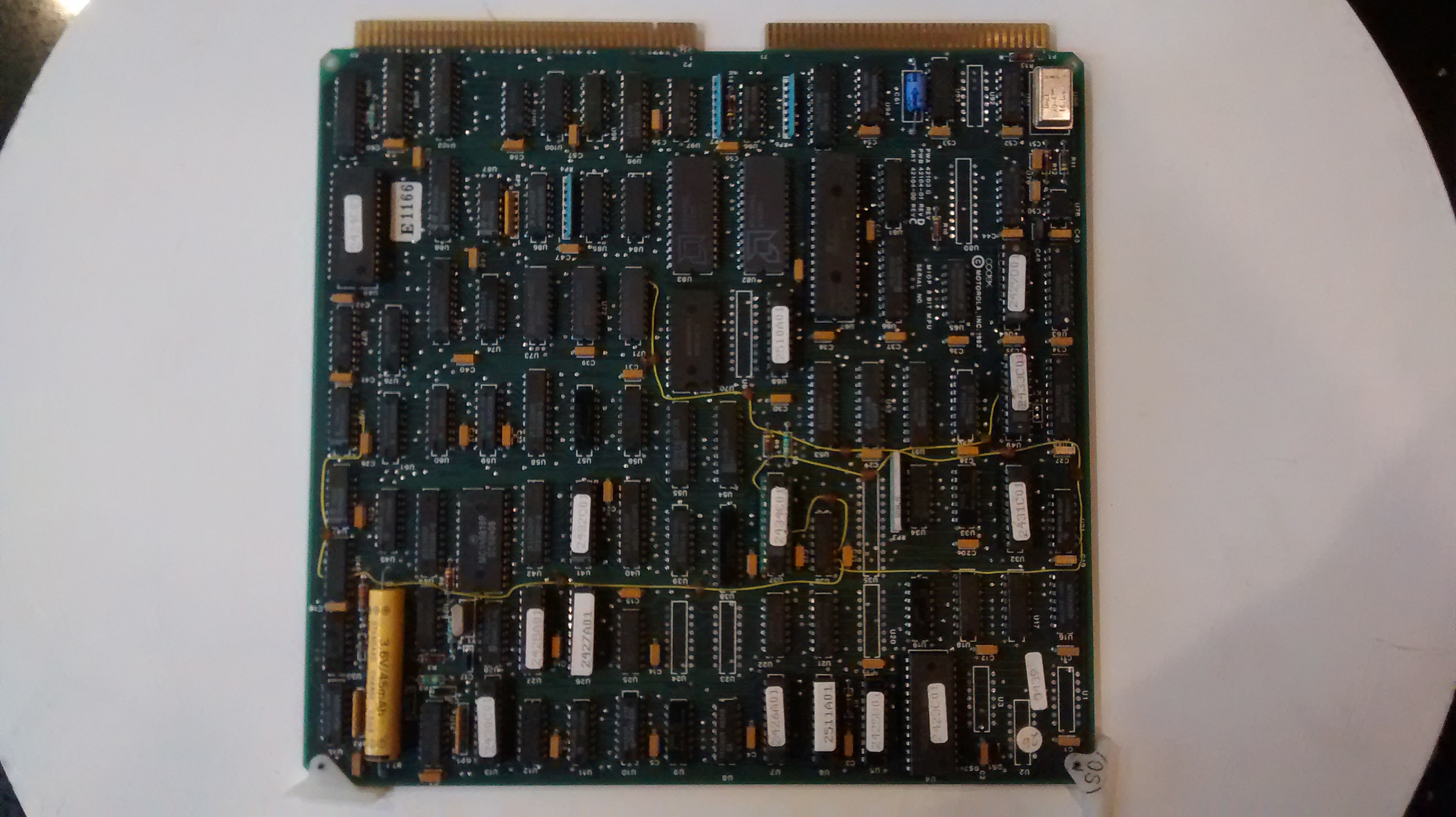
This is a new one on me and a curious one at that. A quick search of the internet found a small piece on http://en.wikipedia.org/wiki/Four-Phase_Systemsbut not a great deal and nothing on the company after they were sold to Motorola in 1981.
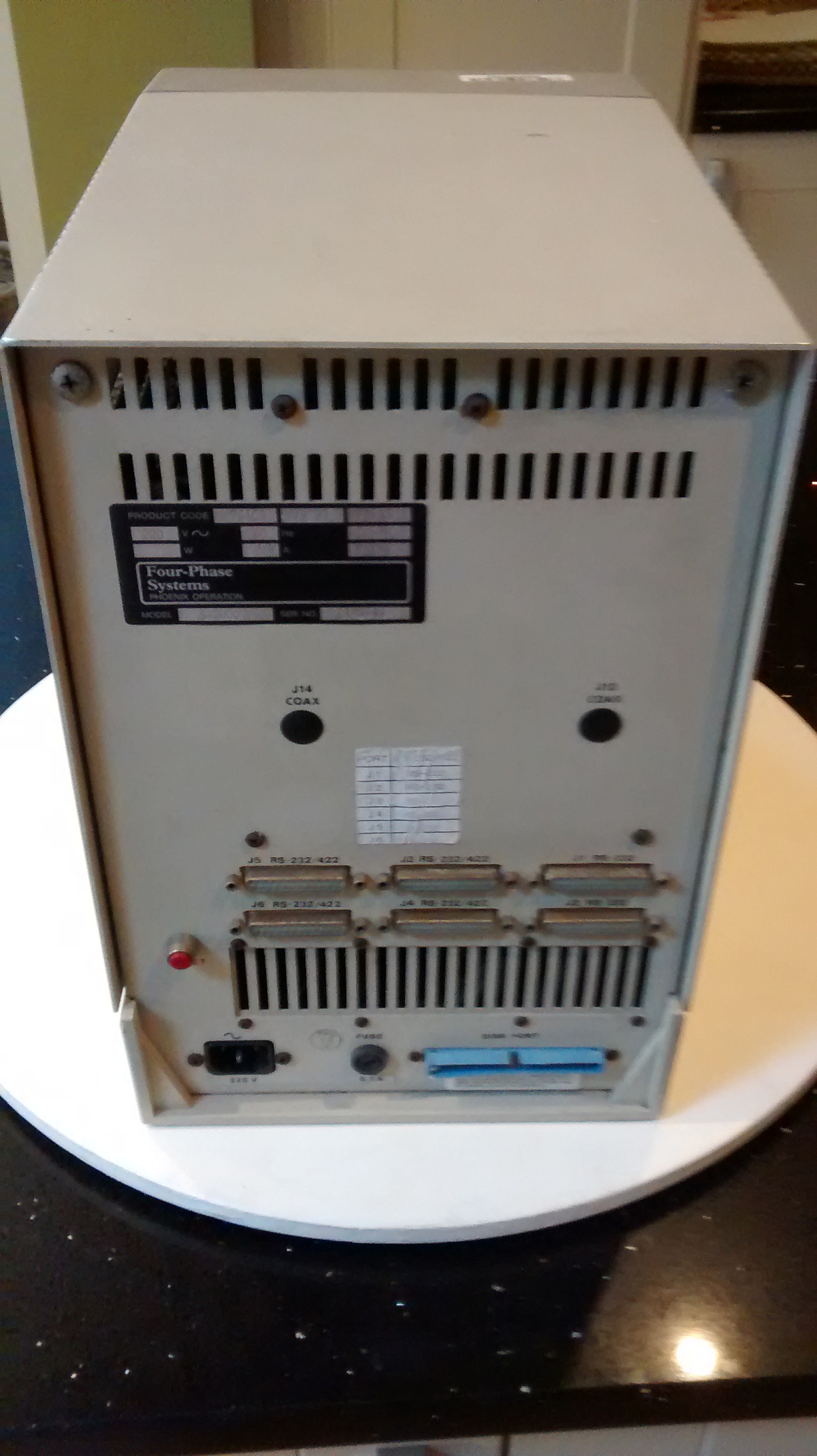
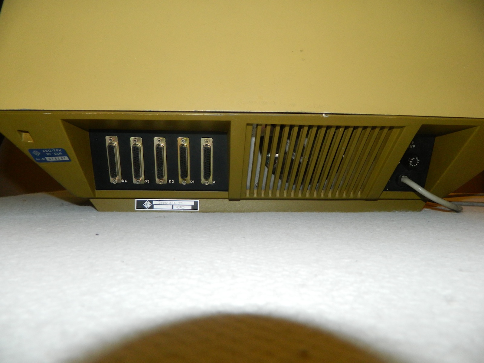
The machine we have here appears to be a small office machine; It has six serial ports on the back along with a 50 pin connector for an external disk drive. I’m guessing SCSI but I have no proof, I have no disk drive either.
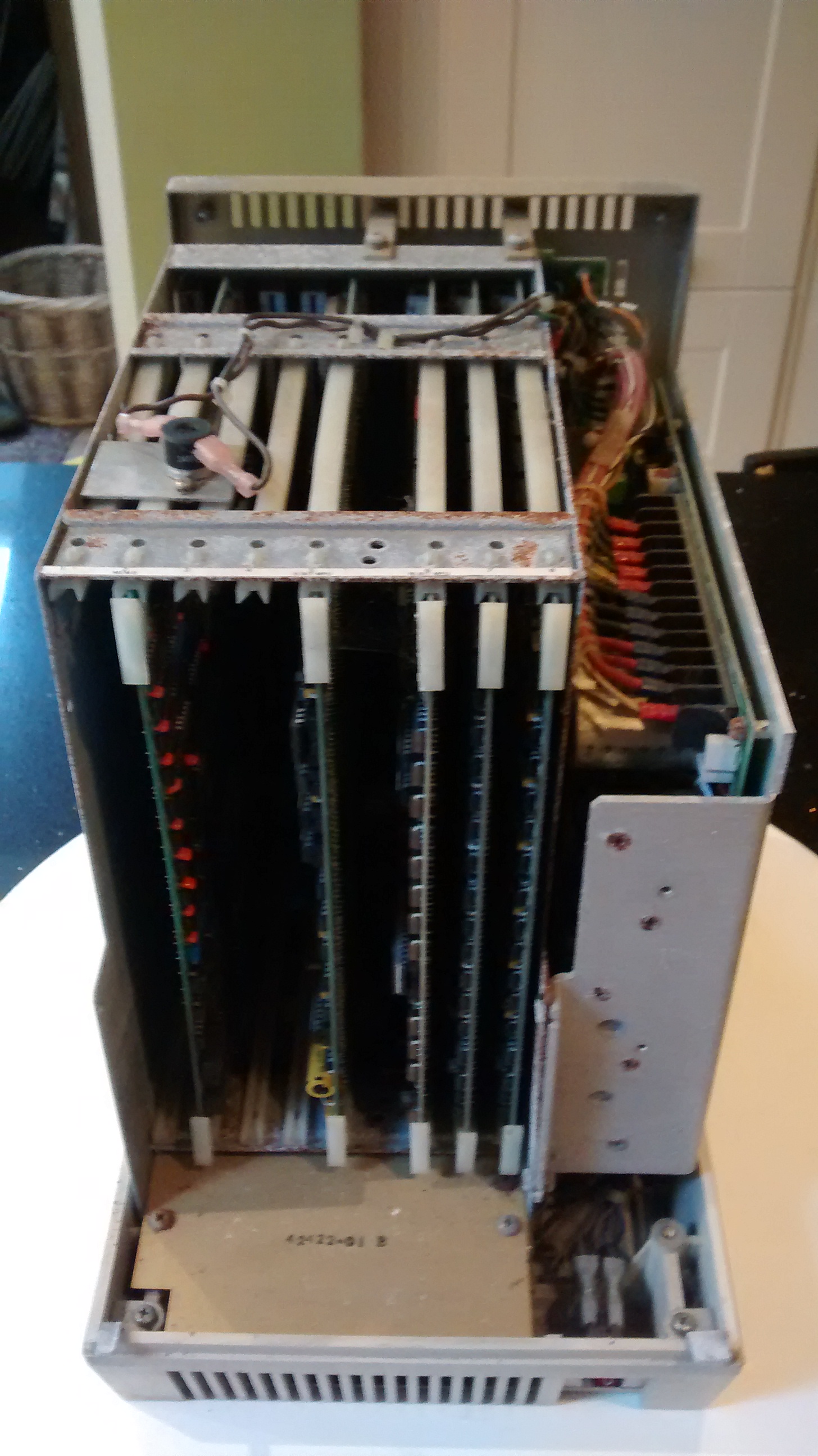
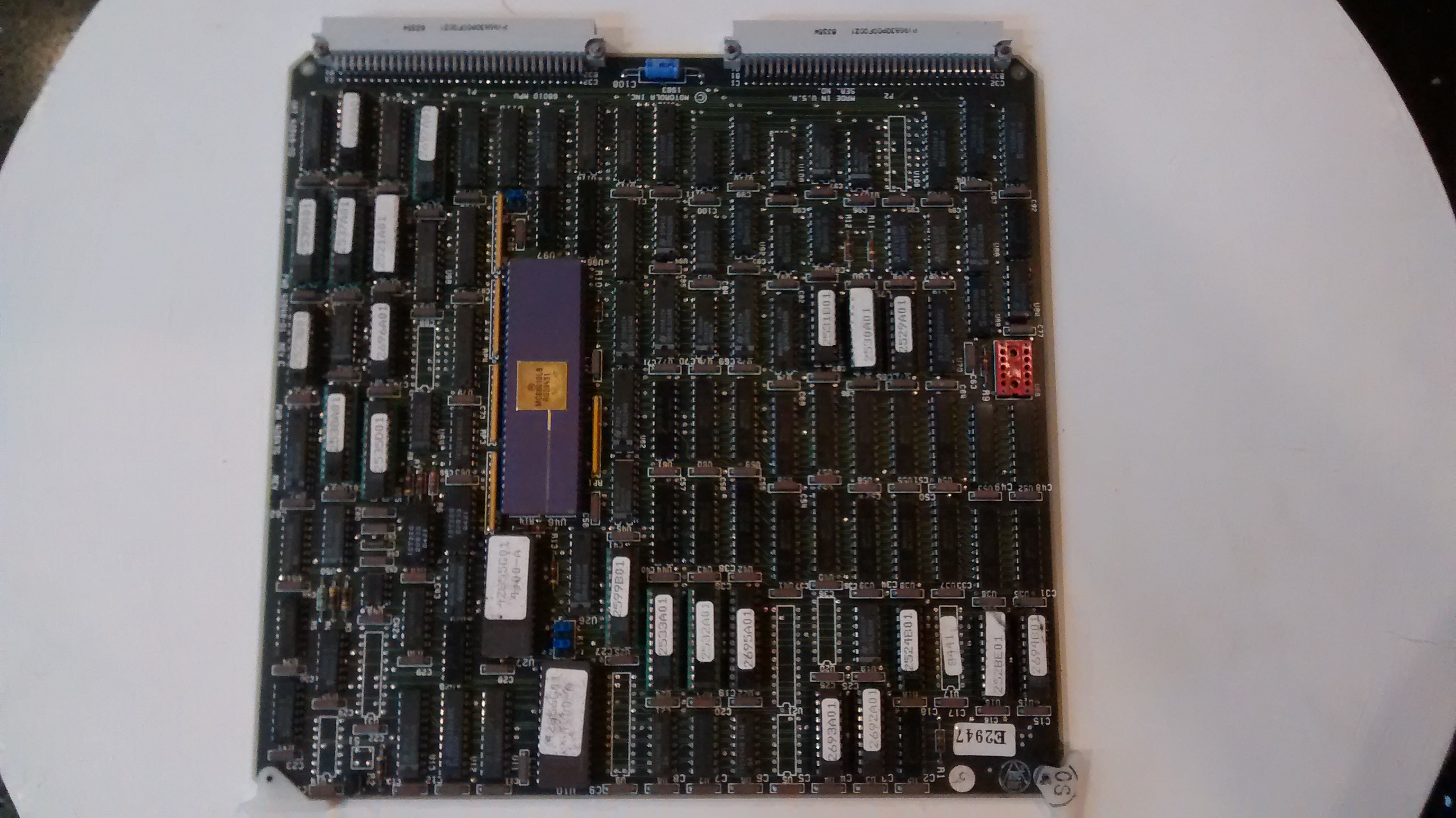
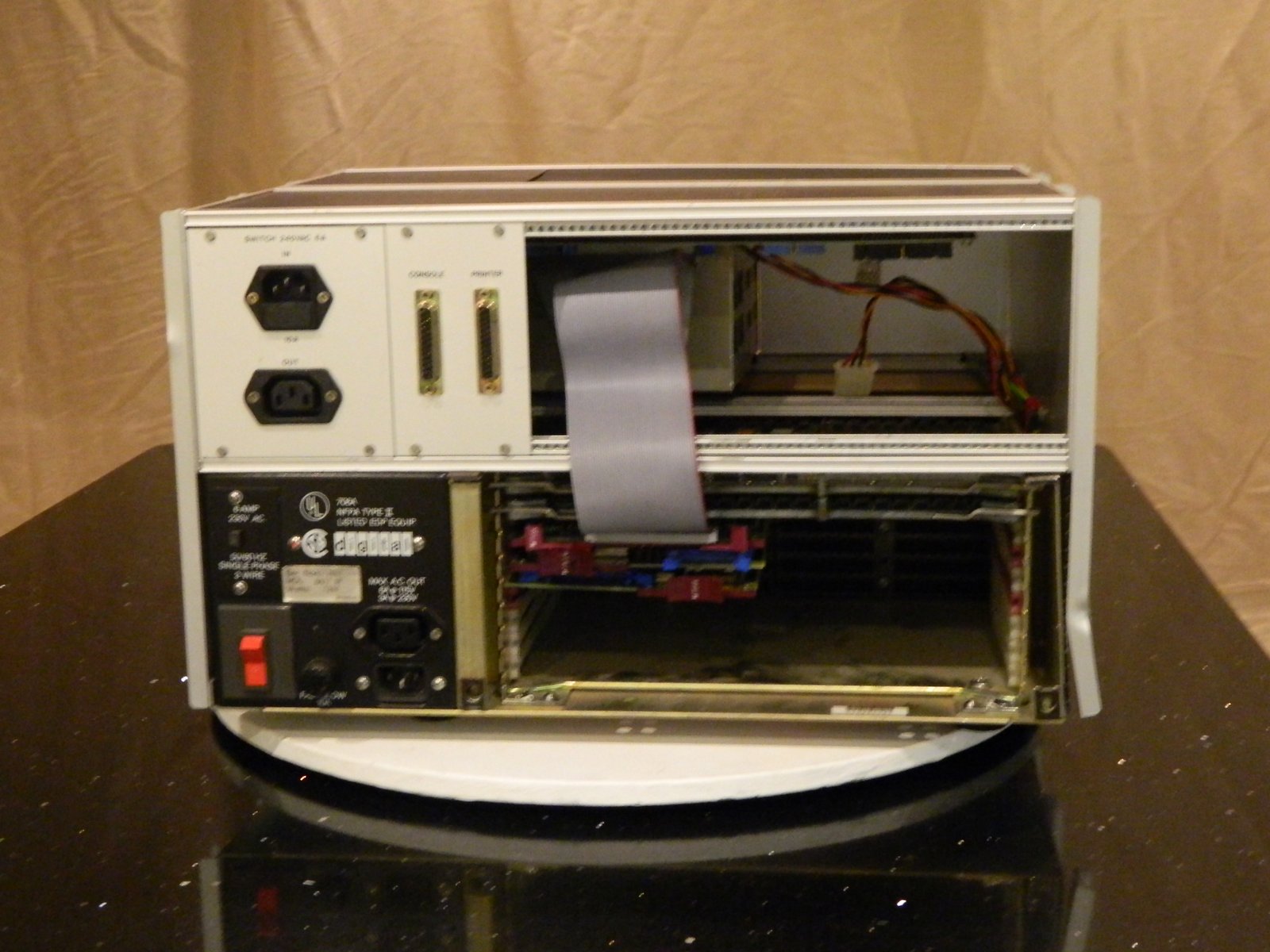
Inside the case is a card cage but it’s a bit stranger than it first appears. There seems to be two buses in the cage. The two boards on the left have card edge connectors and both have 6809 processors. The three boards on the right have three row connectors with pins that look like connectors on a VME bus. One board has a Motorola 68010. The other boards seem to be RAM cards.
When I power the machine up the fan whirs and I can see a couple of LEDs glowing optimistically. I don’t see any activity on the 25 way D type at the back labelled “J1 RS-232”.
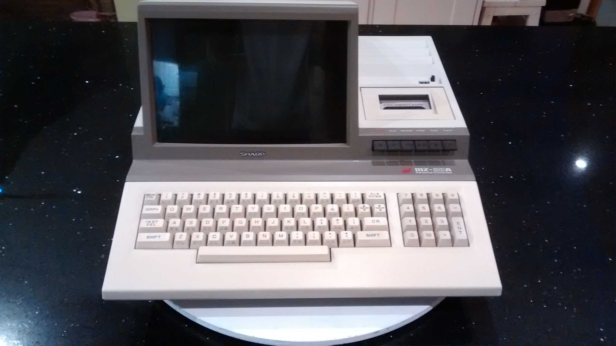
The Sharp MZ-80A is an all-in-one machine that’s of a style that was not unusual in the early 1980’s. Think Commodore PET, Intertec SuperBrain. Televideo TS-802 and 803. Even the humble Amstrad PCW range.
The screen Measures approximately 9″ diagonally and has a clear plastic plate in front of it. This is rather reflective as you can see in the above photo. The keyboard is full sized and the keys have a good degree of travel. There is also a number pad on the right.
A cassette recorder is built into the case along side the monitor and to its right. This records at 1200 baud (approx 120 characters per second).
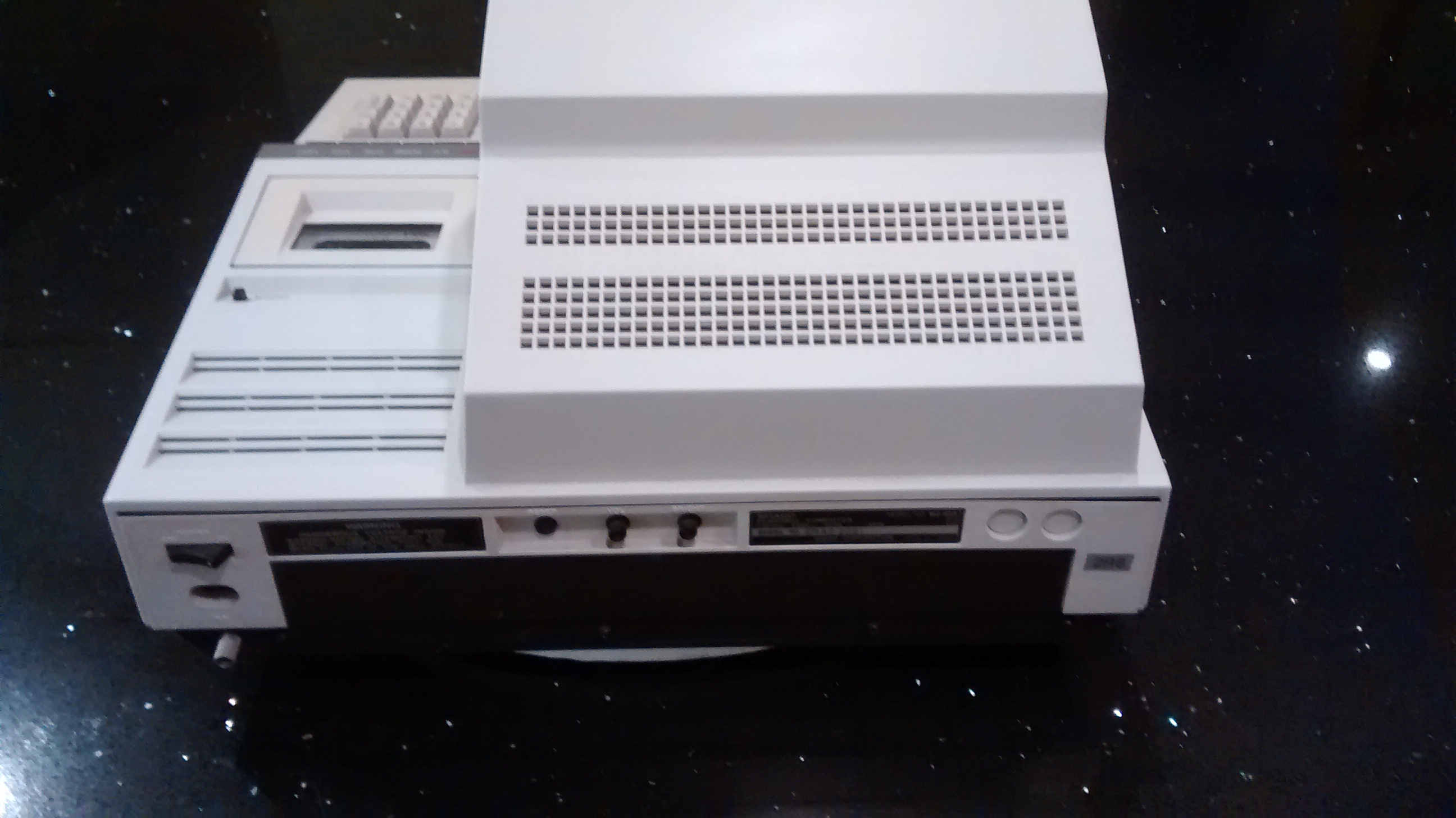
At the rear of the machine there is a figure 8 mains socket and rocker switch for power, the brightness and contrast knobs and a reset button.
Additional ports such as Centronics parallel and RS-232 serial are lacking though I believe they were available as an option. There is certainly space inside the case and the main board has an expansion connector heading off into the empty space at the back.
Rather unusually, it doesn’t have a resident BASIC interpreter. Instead there is a monitor ROM with very few commands and BASIC and other languages were available on cassette tape and loaded in as required.
A friend at work, knowing that I was interested in retro computing, arrived one day with this splendid example of a Commodore 4032.. Sadly when I powered it up I only got a “Bingley beep” sound but there was at least some signs of life.
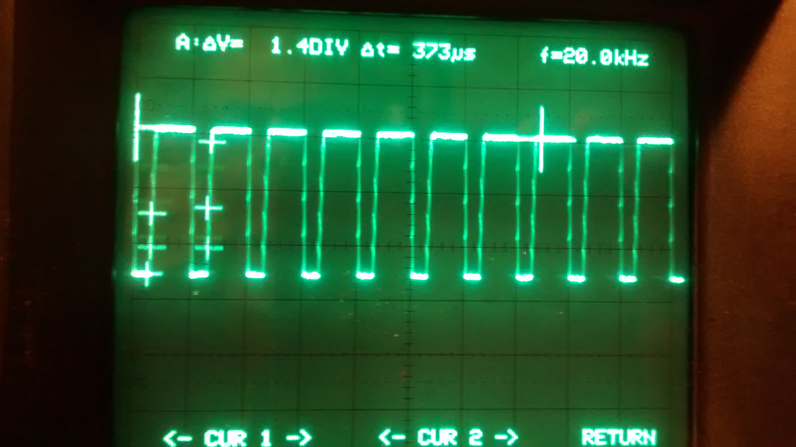
I moved around the board with a scope and found the clock looked good, as did the horizontal and vertical video signals.
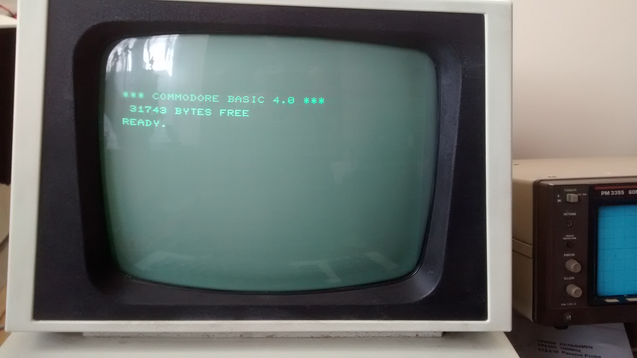
More searching found that the _INT_ line to the 6502 was low. I reasoned that it should be mostly high. The 6520 PIA controller driving the IEEE port is connected to that line and as I didn’t need IEEE at the moment I pulled the chip out. Power up and Bingo! now running.
Having read through a few hastily translated bits of the technical reference manual I felt that I knew enough to try and get the floppy drives connected. I wasn’t given an original cable but looking around the back of the card cage and at the drives themselves it looked likely that they needed a 25 Way cable (the manual didn’t say).
Powering up the
drives without the cable seemed OK though they did sit spinning. 5 1/4 drives don’t
start until they are needed (usually) but I don’t know what 8 inch drives generally
do.
Switched everything off. Plugged in a cable. Disks on. Main unit
on….
Drive light comes on for a bit and then goes off. Whoopee.
This is repeatable 🙂 I have since tried a floopy in the drive and get
the same behaviour. I can’t get it to boot but I’m delighted to have got it this
far.
In the previous post I got the PDP-11 booting from a tape emulator into the diagnostic system, XXDP.
Next I wanted to move on a bit.
I was given some boxes of RX50 diskettes by a friend of mine. DEC kit can be very picky about floppies and generally wants them pre-formatted. The PDP-11 is no exception. It is possible to format them on a PC I believe but I don’t have a PC with a 5.25″ floppy drive.
I booted the PDP into XXDP and then used that to initialise a floppy diskette. this doesn’t format it, just writes some structure to it.
I next used the COPY/BOOT and COPY/FILES commands to make the diskette bootable and have all of the files that are on the tape.
I was a complete novice with the PDP-11 and so I asked for some help on the www.vintage-computer.com forums. Thanks to the help of the folks there I got the machine to boot.
This is what I did…
Downloaded the TU58 emulator from Don’s site here. This enables a PC to emulate a TU58 which is a tape drive unit that talks to the PDP using a serial port. I downloaded a disk image for the TU58 emulator to load and present to the PDP when asked, from here.
I used Win Xp on my rather old laptop and used Hyperterm on COM1 (19200) to act as my terminal to the PDP. I started a command prompt on Xp and then started tu58em with the options -p5 -s 9600 -r 11xxdp.dsk. This starts tu58em talking on COM5 at 9600 baud with the disk image mounted as read only.
I had COM1 connected to the console port and COM5 to the printer port.
I started the PDP, watched it go thorough its self test and the numbers 1 to 9 and when it started rattling the RX50 I pressed ctrl-C to break the boot. It asked for a command and I used…
Code:
BOOT DD0
and watched as it started up.
One point I didn’t pick up on until I saw it was that it has both DD0 and DD1 are on the same port. I thought they would be on two serial lines (SLU) and they are not
Now I’ve booted up the PDP I’ll sit down with the manuals and boot myself.

 However. It hands after a minute of so. A restart and it only lasts seconds and so I’m convinced that it’s thermal. More investigation needed.
![IMG_20150310_192638665[1]](http://www.randomorbit.co.uk/wordpress/wp-content/uploads/2015/03/IMG_20150310_1926386651.jpg)
![IMG_20150310_193434344[1]](http://www.randomorbit.co.uk/wordpress/wp-content/uploads/2015/03/IMG_20150310_1934343441.jpg)
![IMG_20150310_211215630[1]](http://www.randomorbit.co.uk/wordpress/wp-content/uploads/2015/03/IMG_20150310_2112156301.jpg)